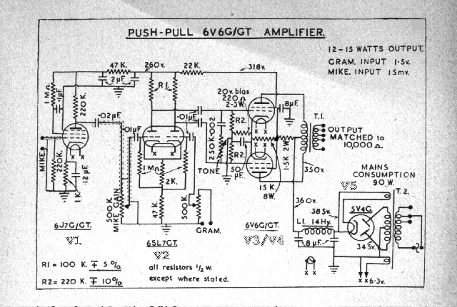

A number of people entering this hobby (or are more experienced experts at cabinet and appearance restoration) regularly pop up with questions as to the nature of the circuits of the old grand and what might appear electrically enigmatic instruments we have at hand. It is with such folks in mind, together with younger people developing an interest as well as those retiring who finally have enough time to get down to this work, that I present a couple of circuits from a long-forgotten valve manual, together with a few comments as to their operation. Very many such amplifiers or radios had similar circuit arrangements, differing only by the addition of a tone control, single-ended or push-pull audio outputs, a gramophone input, or parallel / series heater chain connections. Some ran straight from a D.C. mains supply or a battery, some had mains transformers (or "line transformers") for A.C. use only, and some had rectifiers and resistor "droppers" for use of either A.C. or D.C. at different line voltages.
This is not intended to be an exhaustive, or overly accurate, tutorial, just an introduction into the ideas behind some of the circuts that follow, so I'll put my (un-earned) teaching hat away for now.

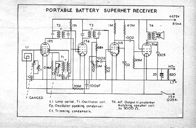
Next we'll look at a simple portable radio intended for battery use. It uses
only 4 valves (no rectifier being neccessary of course). The fewer valves in
such receivers, the less current drawn, meaning longer battery life. It operates
only on the one band, at that time there were not so many stations spread over
medium- and short-waves as we are faced with today! Let's first see the
diagram:
Being a portabe receiver, it
was not designed to have a connection for a long-wire or other external antenna,
so the first part of the set is a loop aerial which is tuned in step with the
local oscillator so as to be effective wherever the set was tuned to. Its'
output is connected to the signal grid g3 of the mixer valve V1, but is not
grounded at D.C., rather it is decoupled at R.F. by the 0.05uF capacitor at its'
'earthy' end; more of which later. The g1 of V1 is connected to the oscillator
coil primary, the secondary of which is connected to g2 (and g4); g2 acts as the
oscillator 'anode' and varies in frequency due to the ganged tuning capacitor
across the coil primary.
In this way, in the one valve, we have both the
wanted signal and the oscillator signal (separated in freqency by the
intermediate frequency where we perform some amplification) and the difference
(intermediate frequency, which is a constant) appears at the anode where it is
selected (and other products rejected) by I.F. transformer T2. This is
double-tuned for extra selectivity and for ease of coupling, tuning being
effected by ferrite or iron-dust cores with a screwdriver slot. Never force
these, they break easily, and do not actually use a screwdriver because of its'
magnetic prperties: use a non-ferrous tool.
The output of T2 feeds g1 of V2,
the I.F. amplifier, the 'earthy' end of T2 secondary again being decoupled
rather than connected to ground/chassis. V2 is a straightforward I.F. amplifier,
a pentode for lower noise and AGC here (see later) feeding a transformer T3
which is very similar to T2.The output of T3 secondary is rectified by the diode
part of V3, developing a negative voltage which is fed into the 3.3megohm
resistor and then the bias for V1 and V2. Now these valves have a useful
characteristic not common to all valves: the more negative their control grid
voltages, the lower their mutual conductance. So if you have a very strong
signal, possibly too large for one of these valves, then the negative voltage
produced by the rectified I.F. will increase, duly increasing the negative bias
on these valves and thereby reducing their mutual conductance, and hence their
gain. In this way, we have 'automatic gain control' (agc) sometimes called
'automatic volume control', and that is why the grids of V1 and V2 are not
grounded to chassis/0V but decoupled by that 0.05uF capacitor. The reason for
the 3.3 megohm series resistor is, in conjunction with the 0.05uF capacitor, to
avoid normal audio amplitude variations affecting the gain - it forms a low-pass
filter.
The audio component of the rectified I.F. is smoothed by both 100pF
capacitors and is fed to the volume control which feeds the audio pentode preamp
in V3 acting as a voltage amplifier, the output of which feeds the output
tetrode V4 which operates in single-ended mode. The grid bias for this output
valve is provided for by applying the H.T.+ for the rest of the set via a 820
ohm resistor in the negative line: this has virtually no effect for the rest of
the set but develops enough negative voltage with respect to chassis/0V for
biassing the output valve, which feeds an output transformer matching the 5000
ohms of the anode to the loudspeaker.
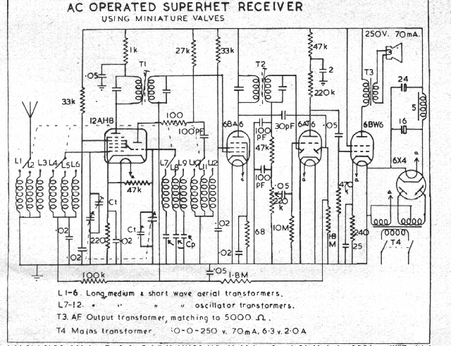
The last circuit shown here is a mains-operated set, using miniature (younger) valves. The basic principles are the same as in the portable set described earlier, so I shall not go into so much detal; rather I'll just mention the more important differences. Before the circuit, some basic aspects. Since this is a mains operated set, there is far less importance placed upon power consumption: it uses some 4 times the H.T.+ voltage at only marginally less current. Also, since it would 'live' in the living room or the study, a permanent aerial/antenna connection woulb be expected to be used. Also, since by this sets' time there were far more stations on more bands, there are three switched bands, eached tuned, rather than just the single knob. Here is the circuit:

The first thing to note is that the mixer valve is a double-valve, a
triode-heptode. The triode functions as a stand-alone oscillator but its' g1 is
internally connected to g3 of the heptode. Aerial signals, from the switched
coil, are coupled to g1 of the heptode. Some bias is obtained from a cathode
resistor, bypassed at R.F. by the 0.02uF capacitor. In other ways the heptode of
V1 can be likened to the heptode of the portable set.
Likewise, the I.F.
amplifier V2 has the same functionmality and nearly the same circuitry as that
in the portable set. Automatic gain control is still obtained from rectified
I.F., but in this case is coupled from the primary of the last I.F. transformer
to a separate diode detector in V3 - in this set it is said to improve the
performance of AGC when there are very close interfering stations (the
selectivity of T2 secondary no longer being of influence). Amplitude-modulation
audio is taken from T2 secondary in the same way as in the portable set
described above. The audio voltage amplifier in this set is a triode rather than
a pentode, but is still operated as a voltage amplifier feeding the output valve
V4, a tetrode. Bias for this tetrode is developed by its' own cathode resistor,
which is decoupled to audio by the 25 uF parallel capacitor.
The rectifier
valve used here is again a full-wave type but with separate cathode and heater
connections: the heater-cathode voltage rating is sufficient not to require a
separate heater winding as was the case with the 6V6 amplifier unit.
I hope that the above notes and descriptions have been of some help to some of you - compiling some of this has been something of a mammoth manual task so I do take a day or so's rest now! All the best in your restoration work.

 You can E-mail the author of these
pages (Trevor Gale) by using this link. on
the Dutch Internet service provider XS4ALL.
 Click on this link to go back
to my main valves page.