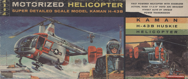
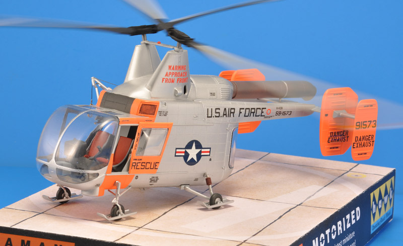
Hawk 1/32 H-43B Huskie
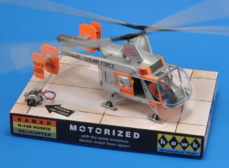
| For a club project revolving around fictitious shop displays, I took over this ancient (1961) Hawk model from club member Leo Ripken. 99% of my aircraft models are 1/72 fixed wing types, therefore a 1/32 helicopter was quite a deviation. Add the early sixties engineering, plus very brittle (aged ?) plastic, and it becomes even more 'interesting'. Because of the club project's theme, I built it mostly straight out of the box, with the exception of the motorization and the decals.
|
The kit
Most of the parts were loose in the box, and that made me worry whether it was complete. Luckily CyberModeler has a Testors 1/32 HH-43B Huskie Kit First Look, with photos of all runners and parts. That helped a lot. I did another check following the construction manual, and concluded that one part was missing, a shock strut for the rear landing gear leg. I will have to scratch-build a copy, or maybe cast a copy.
Next worry were the transparent parts. They had been flying around in the box full of parts, and most notable the front transparancy was scratched, on the inside. Luckily a buffing session with Tamiya Polish made the scratches disappear largely.
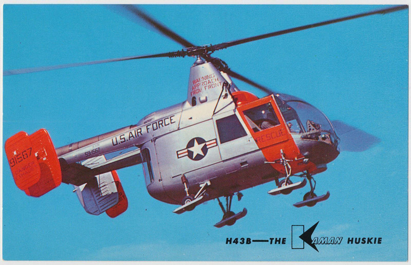
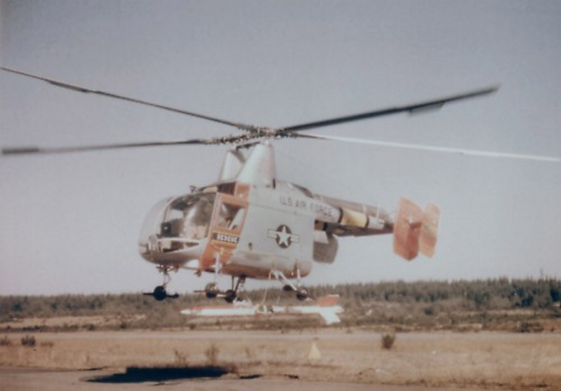
The last difficult decision was how to build the kit. Hawk suggest a silver with orange scheme, of which I found only a single photo. I investigated the color schemes (see below) and concluded it's a mix between the first and third schemes. There's also the South-East Asia scheme, that looks good on the Huskie
| 
|
|
| The old plastic was difficult to work with. It was far more brittle than what I am used to, and the on a few occasions I unexpectedly chipped off a chunk of plastic. I don't know whether it was the age of the plastic, of the plastic composition of the time.
The kit has tons of rivets. In this large scale they are probably not too much oversized. Because I needed to replace quite a few near glue joints, I measured them on the fuselage side. They are 0.4 mm with a pitch of 0.86 mm. https://www.aviationmegastore.com/search/LH85714fc09ad73dd1d1a0ea64f8/rivets/p1/c/s/f3266>
The model of course lacks some details, not strange for a 1961 model. A few things that I noted:
the wire cross bracing between the tailbooms (see Ragay p28, 70 and 75)
the various struts to stabilise the tail surfaces (Ragay p89)
the spartan interior, for which a Cobra Company resin set was available. It is now available from Lone Star Models (LSMCC 32009 Interior set for Hawk Kaman H-43B)
there are two grilles on the forward side of the engine pod, but all photos I've seen show three, one extra on the left side
|
Construction
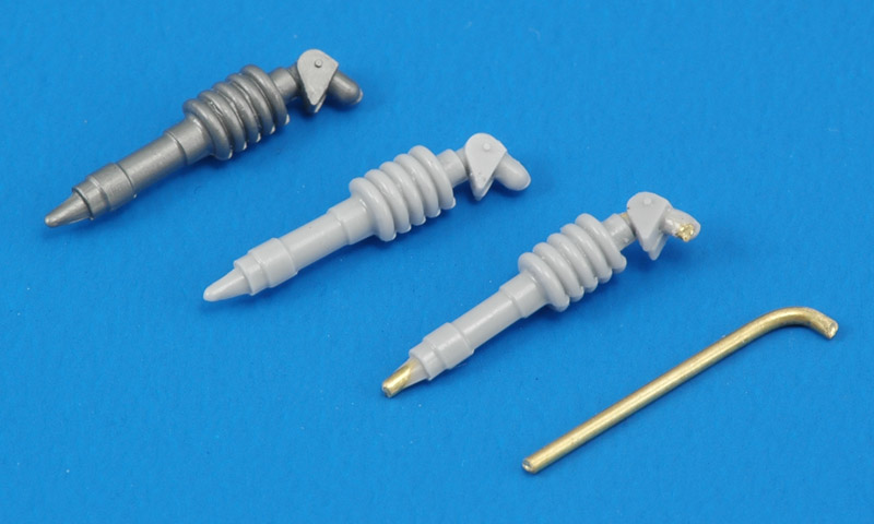
| First job was to cast a copy of the missing part 47, the rear landing gear strut. When I removed the original part from the silicone rubber mold, the part itself failed between the bracket and the spring. I doubt it would have carried the model without breaking! I first cast a normal copy, but in the second one I inserted a 1 mm brass wire for strength. That worked beautifully.
| 
|
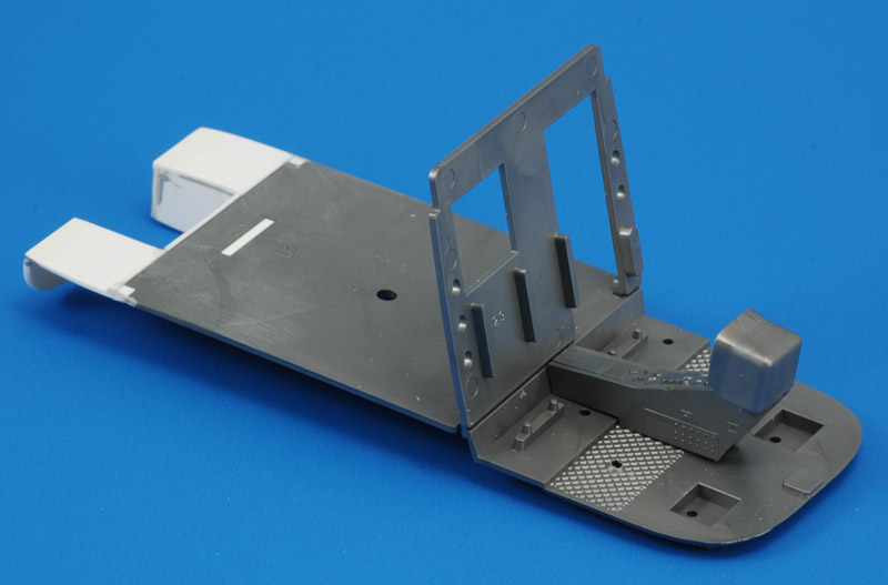
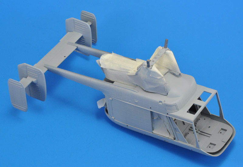
| My approach to building this model is a bit hazy. I wanted to build it straight from the box, but I disliked the motorization features. So I removed most of them, while keeping the rest box-standard. For the cabin this meant an extension of the floor and filling the slot for the electric motor bracket. I gave the floor panel a cut-out like I saw in the rare cabin photos. The dimensions were guessed. I did not worry too much because the rear doors would be closed.
|
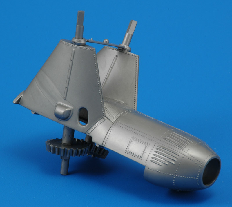
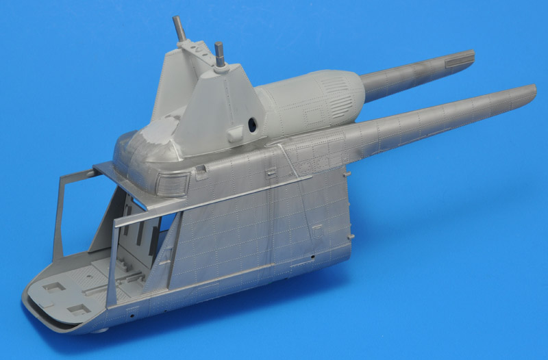
| I assembled the twin rotor pylons as per instructions, again using great care in the gluing. I assembled the turbine housing similarly, and glued it to the pylons part. It surely was a challenge to build so cleanly, but the result is nice.
| 
|
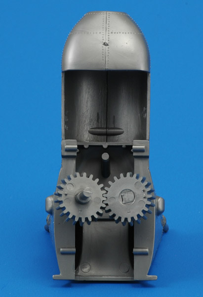
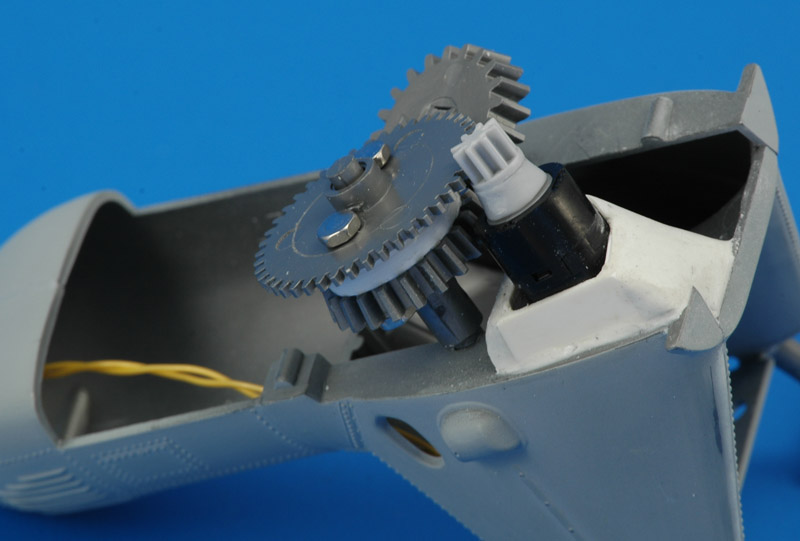
| With the engine/drivetrain housing assembled, a study of the modern motorization possibilities was done. I first expected to install a fairly large geared motor in the turbine area, but then I found a small geared motor that would even fit partially in one rotor pylon. The geared motor was so small that it could drive one of the beveled gears that ensure the intermeshing of the rotors - I did not even need the third gear from the old motorization. This allowed a very clean installation, with hardly anything visible from the outside. The simple (read reliable) installation also allowed the masts+housing to be glued to the upper fuselage, instead of leaving it removable for repairs.
|
| My kit did not include the old Japanese motor, but I still wanted to motorize it. My ideal was a smaller motor that would fit in one of the rotor pylons. On Ebay I found a mini-motor with integral reduction gear, and indeed it fitted almost as expected. It's 25 mm long and 10 mm diameter, 360 rpm at 6V. I positioned it as parallel as possible with one of the rotor axis, boxed it in with plastic card, and then reinforced the box with Apoxie Sculpt. I made the gear on the rotor axis removable, for possible modifications or repairs. It fits with two M2x10 bolts to one of the meshing gears.
| 
|
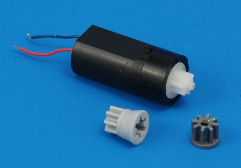
| The mini-motor had an integral pinion, that really did not like meshing with the kit gear. I found a solution by lightly gluing the kit pinion (front right) on it, followed by an Apoxie fairing around the motor's pinion. After curing I could pop off both together, and I cast a resin copy of it (front left). The resin part fits so tightly on the motor that no glue is required.
I overlooked one aspect of the motorization: the noise. The mini-motor screams at full voltage, like a jet engine being started up. I guess I will run it at much reduced power and rpm to keep the noise down. It still allows the observer to study the interesting meshing of the rotors.
|
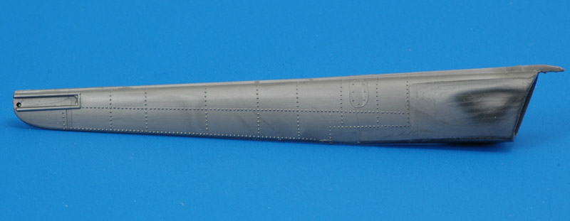
| The tail booms did not lie flush in their cavities. Since sanding was not possible because of all the rivets, I had to improve the fit. I outlined the contact areas and started scraping on the inside. It took quite a bit before they conformed. The old plastic reacted in ways I've never seen in modern kits, with all kinds of color changes.
| 
|
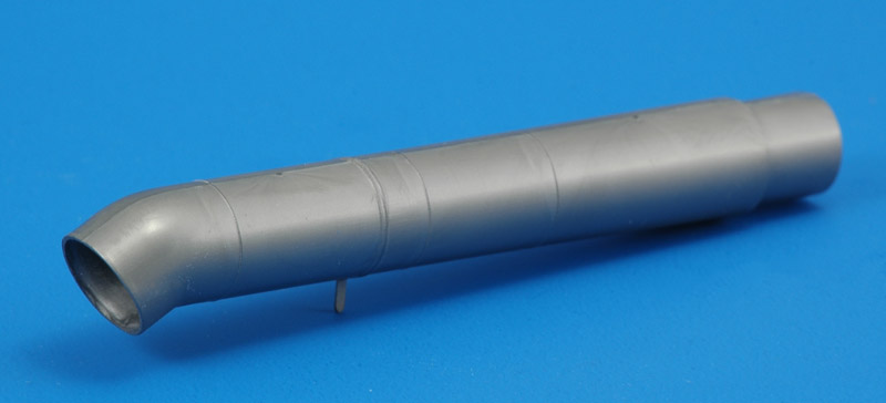
| The two-part exhaust tube required careful gluing and sanding to preserve the raised panel lines (weld lines?). I think I managed. I thinned the exhaust opening considerably, not completely in line with the straight from the box approach.
|
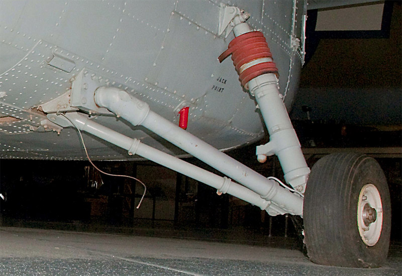
| Initially I wanted to run wires down the fuselage and landing gear to an external power supply, but I could not find a good solution for the wires running through or along the landing gear legs. As an alternative I looked for room for two AAA batteries, and to my surprise they fitted inside the turbine compartment. The batteries themselves would fit, but there would be no room for the PWM speed control. So I went to the original plan to run wires down the landing gear. I looked high and low for methods to integrate the wires in the landing gear legs, but it seemed not feasable. I decided to use the stripped wire wrap wire as a brake line on the rear wheels, as seen in this photo.
| 
|
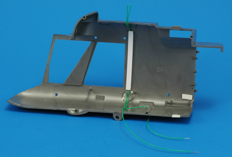
| I made a cable duct on the right cabin wall, as much as possible invisible from the outside. The wire wrap wires were secured with blobs of epoxy glue.
|
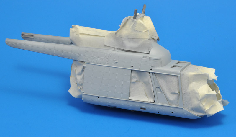
| Fast forward: at this point I made quick progress with the assembly, that I forgot to take photos. I painted the interior MRP-100 FS 36231 overall, and then assembled the fuselage halves plus the cockpit / cabin insert. After connecting the wiring, the pre-assembled engine / drivetrain was CA-glued on top, and the substantial gaps filled with Apoxie. Next, the tailbooms were glued on, and again the gaps were filled with Apoxie. By using wetted toothpicks, the Apoxie putty can be smoothened, eliminating the need for sanding.
| 
|
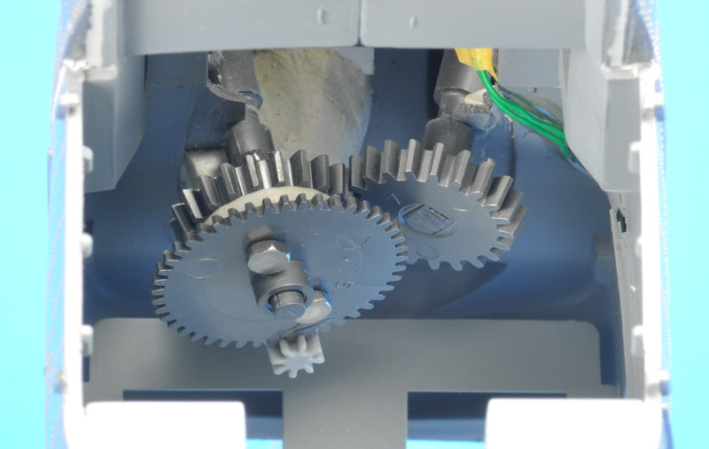
| Here's another view of the electric motor and gears to drive the rotors. The photo was made through the rear fuselage door opening.
|
I wanted to finish the model with MRP paint, but I learned that an enamel undercoat gives better paint adhesion. Enamel paint is also much better suited to small sanding repairs. Therefore I painted the model with my old favorite base coat, Humbrol 127. I painted it much thinner than I usually did.
I reviewed the model closely, and found only problems around the top side windows of the cockpit.
| 
|
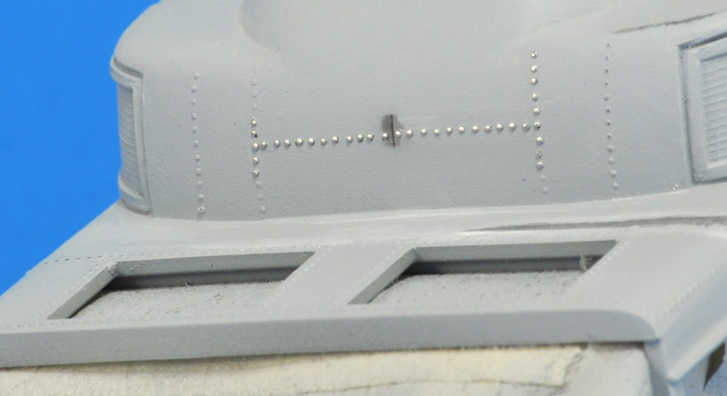
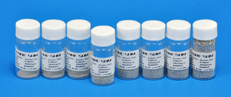
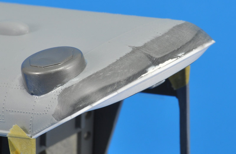
| For a small cosmetic repair, I tried the craziest technique I'd ever come up with. A row of raised rivets on the front of the nacelle had suffered badly in the assembly process. First, I measured the pitch, and printed a paper 'ruler' with that pitch, plus a 5% smaller and a 5% larger version. In the end, I used one with a 0.95 mm pitch. I used that as a guide to make tiny impressions with a needle. Next I drilled shallow 0.3 mm holes, then pressed 0.4 mm diameter solder balls in those holes. I used a wetted tooth pick to grab a tiny solder ball, and push it into to hole. Of course I lost quite a few of those tiny balls in the process, but I had a ton of them.
Next I used the large surface of a fingernail to add some more pressure. And it worked! I got a nice row of rivets.
Unfortunately, I used a hard metal surface to press some more, but I shouldn't have done that, the dome rivets became flathead rivets. I popped them all out, and redid the job, which went a lot faster than the first time. It's always nice to see a learning curve in action :-)
|
Here's the set of solder balls that I bought on Ebay. The sizes range from 0.26 to 0.76 mm. You get 26,000 of each, which should be plenty.
To improve the result, a photo-etched ruler could be made, to improve the accuracy of the hole drilling.
| 
|
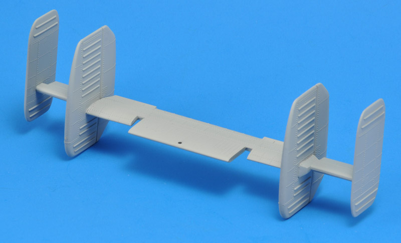
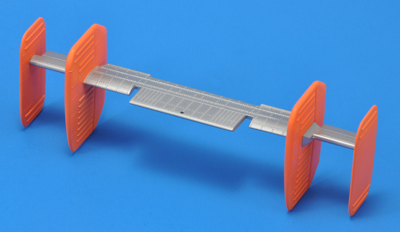
| I assembled the nine parts that make up the massive tail unit. It's a delicate structure - the real thing has lots of bracing that the kit lacks, and I did not want to add. Predictably, I broke off the vertical tail surfaces on one side. It was repaired with 0.75 mm steel wires embedded in the parts. The parts had lots of ejector pin marks that I filled with Mr Surfacer from a bottle.
But I had made a big mistake, and luckily my modeling friend Eric spotted it: all vertical surfaces were inverted.. I had never built a helicopter, and I went for the classic layout of an aircraft tail, with most of the fin area on the top side. That wouldn't work on a helicopter with flexible blades.
|
Two glue joints of the tail assembly were broken, and I had to install steel wire pins (0.75 mm) to reconnect the pieces. These could be bent slightly to fine-tune the alignment.
When I test-fitted the painted tail to the model, I was amazed how big the tail was compared to the fuselage. Not having a tail rotor has its drawbacks too, it seems.
| 
|
| One of the last major airframe parts were the rear doors. I painted them MRP-100 FS 36231 on the inside, then superglued them to the fuselage. All gaps were filled with Apoxie Sculpt, followed by a primer-ish layer of Humbrol 127.
|
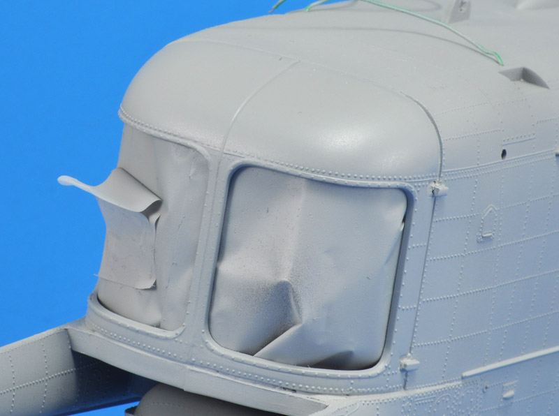
| The fit of the huge front window wasn't very good - it looked like the whole window was too small. The best solution that I saw was to modify the lower side of the window frame (shown inverted here). I glued 1.0 x 0.5 mm strip all around the lower edge, and that pushed the window up to the top of the fuselage. But a 'Bubba Blue' lip (from Forrest Gump) was a side-effect. It was sanded down aggressively, sanding though the plastic in the end. I filled up the area behind with Apoxie Sculpt. The rivetting suffered badly, but I accepted that.
| 
|
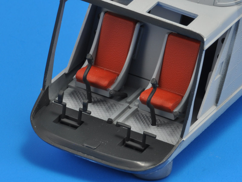
| I had to build the cockpit before I could continue. I started by painting the forward part of the floor Revell 9, and the windshield glue edge too. The seats were given dull red cushions, the rest FS 36321. Control sticks, collectives and rudder pedal all Revell 9 too. Still to be added is the center console, and some kind of box in front of it.
|
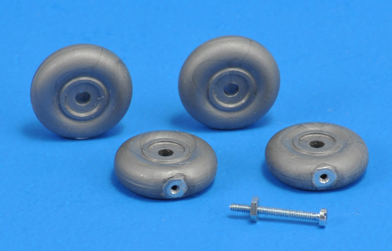
| Tiny M1 nuts were glued into 2.5 mm holes drilled in the tires. The nuts and bolts are made by Krick Modell from Germany.
| 
|
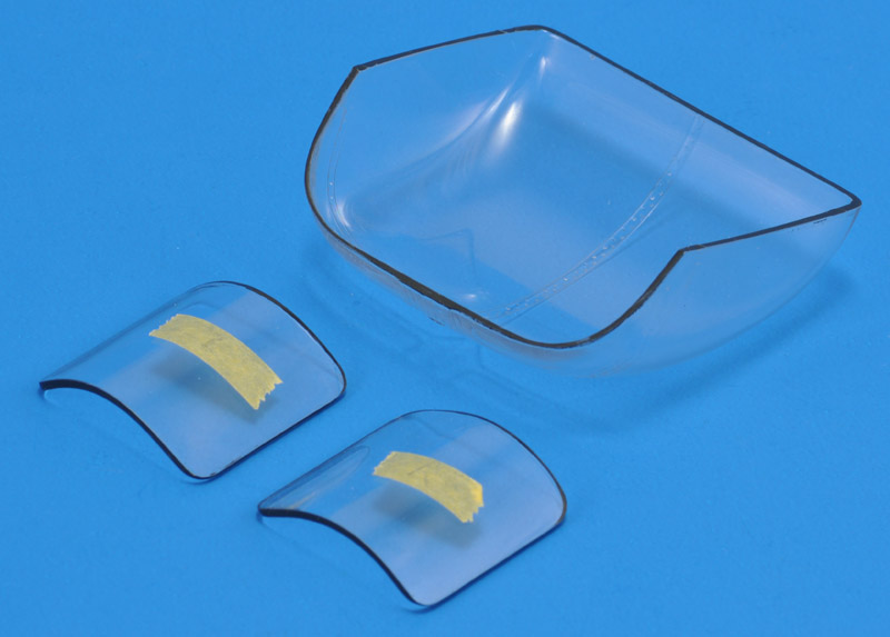
| The windows in the rear doors needed sanding to make them fit. I painted the edges black, and did the same with the large windscreen.
|
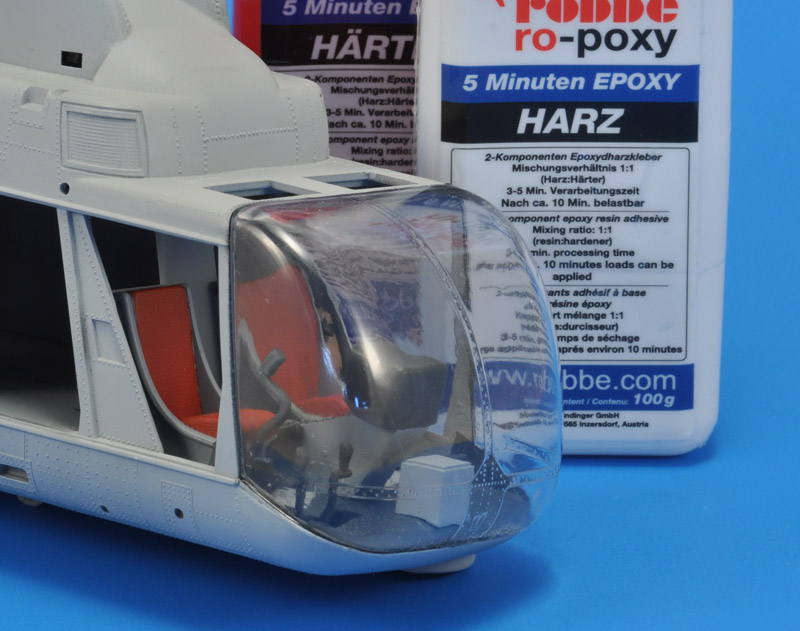
I always glue transparant parts with 5 or 10 minute epoxy glue. Currently I use a set by R&G Faserverbundwerkstoffe, rebadged by Robbe.
The fit of the windscreen wasn't too good, but this is what it is.
| 
|
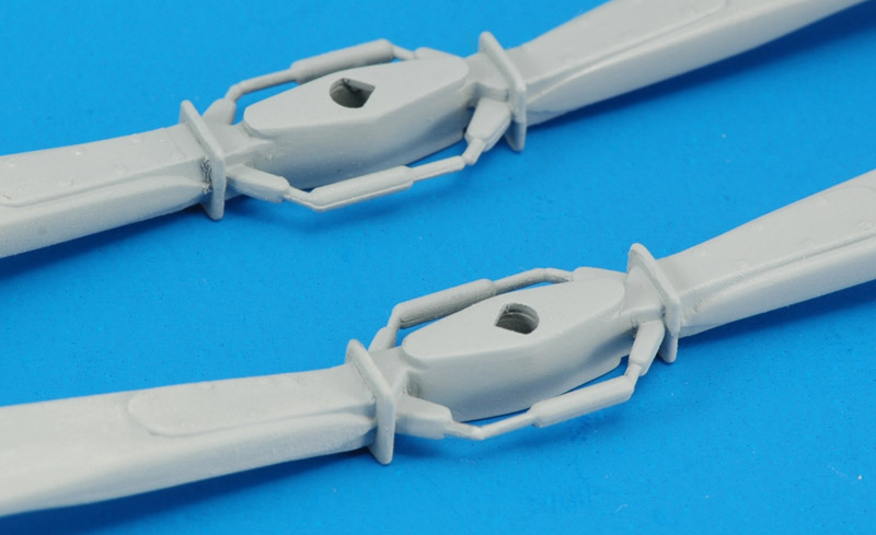
| The rotor blades were assembled from four parts, paying a lot of attention to use the correct parts. The two blades should have a dihedral (V-shape) with the trim tabs attaching to the bottom on the blades. This modeler did not pay enough attention, and it's entertaining to see: Final Reveal Chopper Madness Testors Kamon H-43 Huskie.
The hub assembly was sanded smooth, although the real thing has a multiple bolt connection down the middle. The edges of the rotor blades were also sanded smooth since there was a mold line there. The parts shown here are base-coated in Humbrol 127. Later I glued a small disk cut from 0.3 mm plastic card over the pie-piece shaped opening. This was not completely in line with the plan to build the model straight from the box.
|
Painting
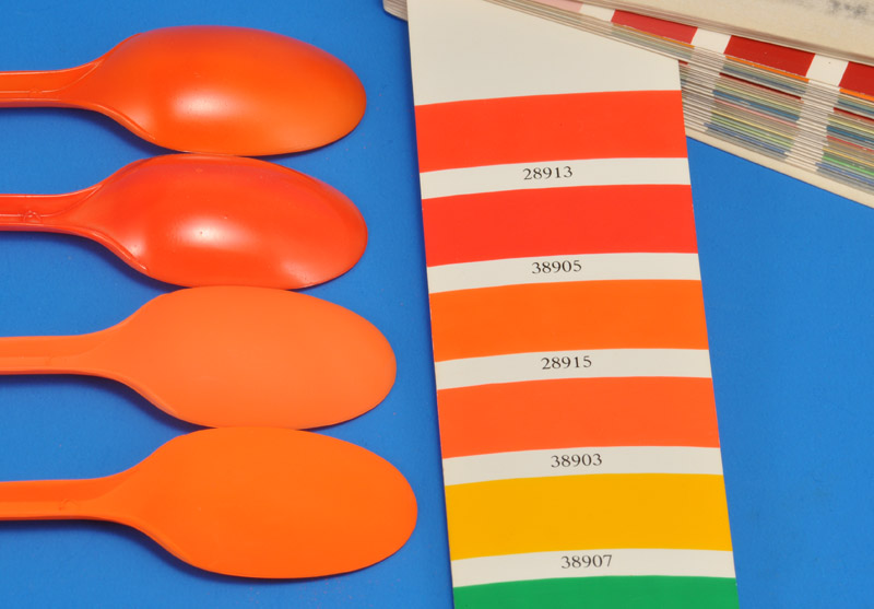
I couldn't find an actual photo of 59-1573, the box art Huskie, so that doesn't help to decide whether to use orange-red (FS 28913) or orange-yellow (FS 28915). Hawk says to use orange-yellow, in the first build step, but I take that information with a grain of salt. The decision was effectively made by paint availability.
I made spoon test samples of four orange paints. Top to bottom: Xtracolor X161 FS28913 Fluorescent Red/Orange, Humbrol 209 Fluorescent Fire Orange Gloss, Revell 25 RAL2005 Leuchtorange and Xtracolor X253 RAL2005 Leuchtorange. Xtracolor RAL 2005 came closest to 28915, but came out very grainy, like I've never seen before. Next best was a very old tin of Revell 25, a bit paler but nicely smooth, and I decided to use that.
| 
|
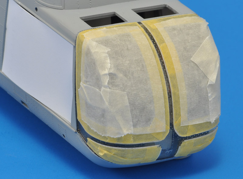
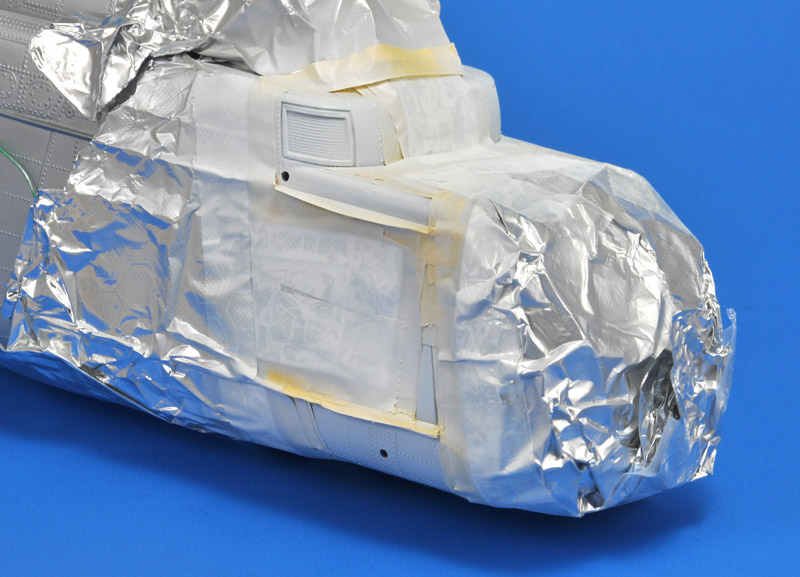
| The windscreen was masked with 0.5 mm Jammy Dog tape and Arctic Decals circular masks, filled in with Tamiya 6 mm tape, followed by 3M masking tape. For the door openings I cut light cardboard inserts.
|
I forgot to shoot a photo of the fuselage painted in MRP-128 Silver, but I think you will believe me.
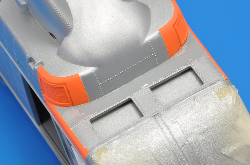
It was difficult to understand the paint standard for the conspicuity markings on the front fuselage: nearly every Huskie showed different details. I decided to leave the rails silver. I could not see where the orange areas above the cockpit ended, so I made my own choices.
I created a curved demarcation on the top, and chose my own demarcation on the front face; the area in between will be matt black, an anti-glare panel according to TO1-1-4. All in all it was a major masking job. I seemed to remember that white should be painted under Revell 25, so I did that, using MRP-004 White.
| 
|
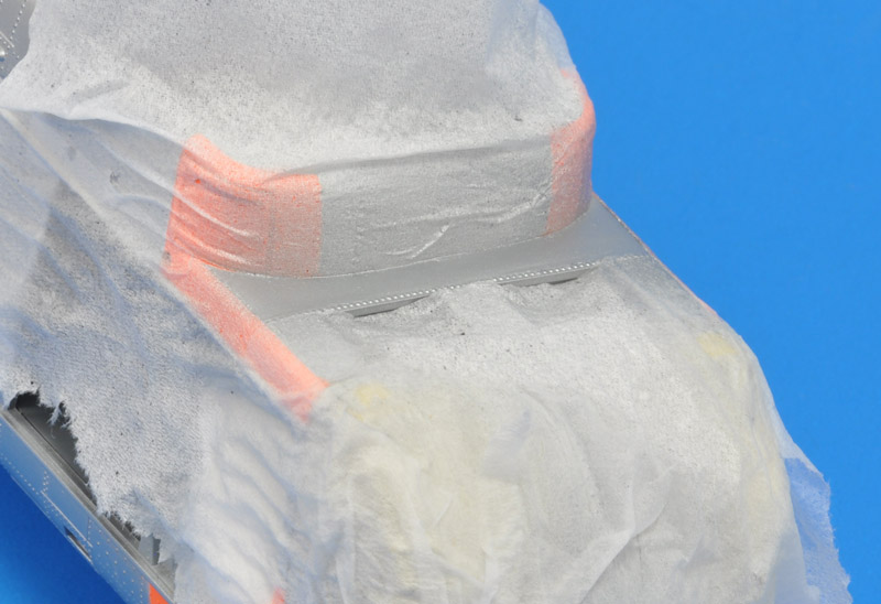
| The masking peeled off large areas of paint above the cockpit. I may have used Novus 2 there, in attempts to smoothen that area. More masking and painting will follow...
|
| To avoid getting into a loop with more masking and more peeling paint, I masked the area with wet tissue paper. This worked so-so: the airflow of the airbrush lifted the edges, and also dried the wet tissue paper rapidly. But the area was repainted successfully.
| 
|
| The masking for the four vertical tail planes was another major task. But the result was rewarding.
|
| The Hawk instructions contain no painting instructions for the blades. Fortunately my photo collection allowed a good study of the colors of the rotor blades. I made a sketch in CorelDraw to summarise the color information. Only after painting the model's blades I noted the black leading edge of the trim flap.
| 
|
| The five colors on each rotor blade required a large amount of masking. I painted the blades first, then I painted the hub. The blades were painted Humbrol 127 op top, Revell 9 on the bottom. Tip colors were Revell 310 chrome-yellow and Revell 371 off-white. The mid gray erosion protection on the outboard leading edge was Humbrol 5.
For the hub I did not have clear information from the photos. I decided on guesswork with black and dark grey.
|
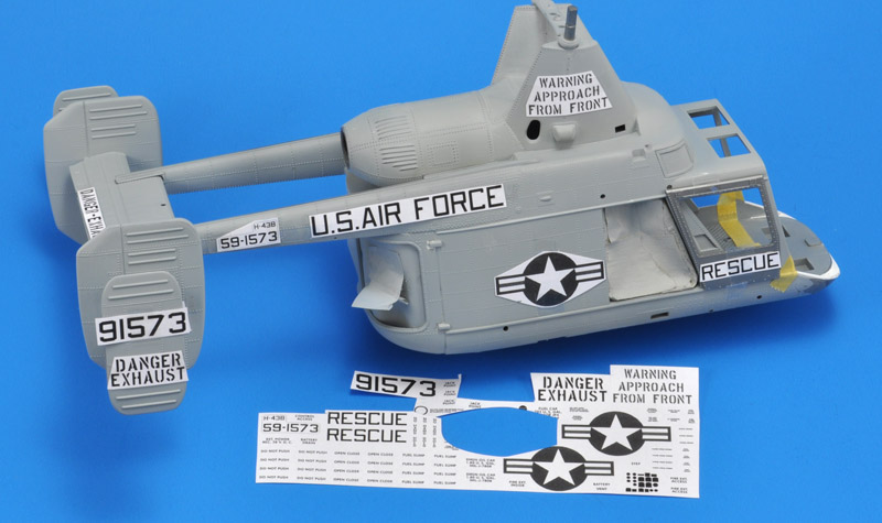
Decals
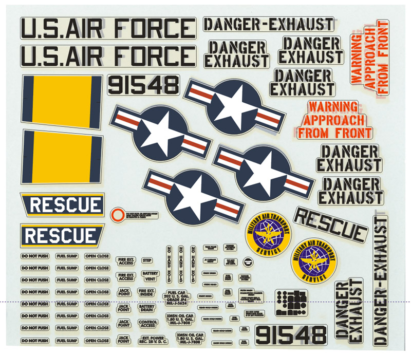
| I did not expect the 60 year old decals to perform well, plus they were yellowed quite badly. I decided to redraw and reprint them. Some comments:
The star-and-bars were 20" star diameter
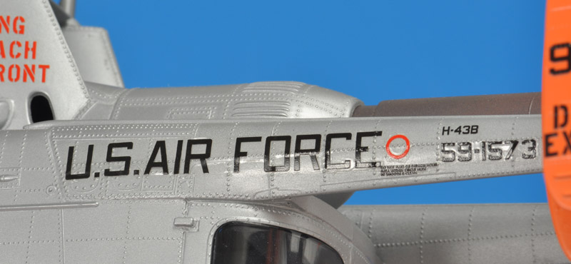
The 'U.S. AIR FORCE' markings were done in the 7x5 grid type lettering, as explained in Appendix 3, 8" height. My assumption is that Kaman applied these marking, but used a Navy-ish type lettering instead of an AF type lettering.
The serial numbers were done in the standard Navy 6x5 grid type lettering, 8" height. They look a bit fatter than the above, hence this choice.
'DANGER-EXHAUST' was done in Reese's stencil, 5" height. The Hawk decal wasn't a stencil though
'WARNING APPROACH FROM FRONT' was done in Reese's stencil, 4" height. The Hawk decal was a different stencil though
The small stencils were done in Futura HvBT, 1" and 1/2" height
|
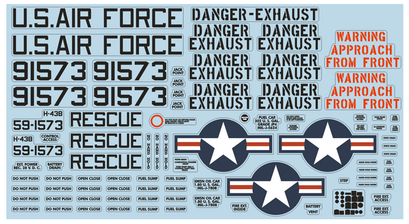
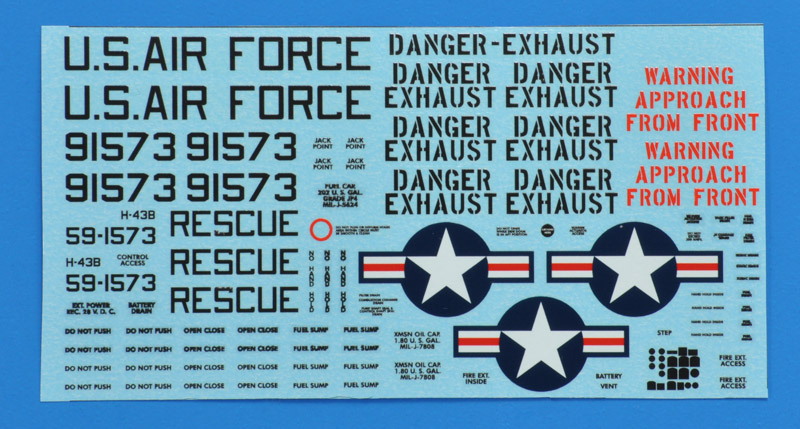
Like a headless chicken, I had redrawn the whole Hawk sheet. But I needed a different set for first color scheme. I found some twenty photos of Huskies in that scheme, and they all differed slightly. I chose the serial number of the box art drawing, and will follow its color scheme. Some comments on this decal set:
there are three instead of four star-and-bars, the one on the engine cowling is absent
4" full serial numbers and 2" aircraft designations for the tailbooms
'RESCUE' in Navy style lettering
I filled every nook and cranny with the stencils
|
| 
|
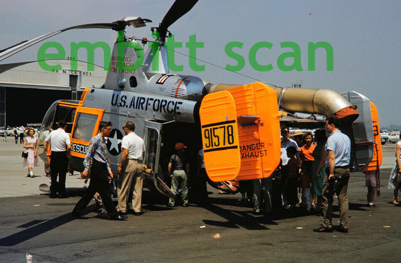
| Usually I want to build a model of which good photos exist. But for this project I decided to build the model as drawn on the box art, serial number 59-1573, a fairly early Huskie. It was delivered and used before the 1962 revision of US aircraft designations, and therefore was a 'H-43B' up to that point, and a 'HH-43B' after that.
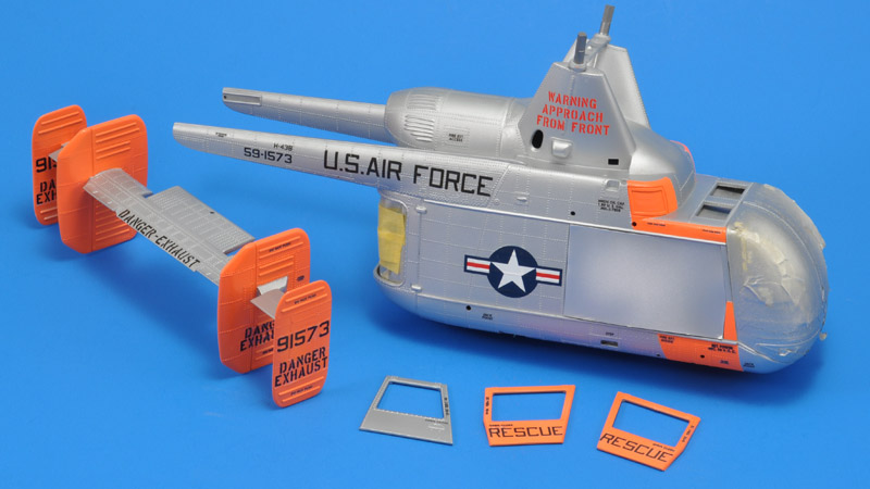
Here's a test fit on the model. The serial number for the tail was clearly too large, so I scaled it down from 6" to 5". The rotor warning text looked too narrow. I increased the letter spacing, and now it looks reasonably good.
|
Here's the printed version, printed by SpotModel. Only when I applied the decals, I noted that a few stencils were missing, both on the original Hawk sheet, and my own sheet:
TIE DOWN (steps 38 + 39)
DO NOT STEP (step 37)
|
| Seven decals were unaccounted for:
|
FUEL SUMP, four left over
FUEL FILTER DRAIN, one left over
STATIC DRAIN, one left over
DO NOT OPEN WHILE SIDE DOOR IN AFT POSITION, no idea where
|
| 
|
| The decaling took a long time, since most decals curled up at the edges, and had to be coaxed down with a brush, a bit of Future and my fingertips.
|
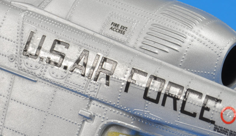
| The large decals that went over a bunch of rivets and raised panel lines, did not conform properly. No matter how hard I pressed on the decals, that would not stay put over the rivets. This made me wonder whether I can apply any clear coat without creating a worse slivering effect.
| 
|
| There was no reasonable quick solution, so I decided to overcoat the decals with MRP-048 Super Clear Gloss, and accept the air bubbles. The clear coat blended in the decals considerably, giving them the same glossiness as the rest of the airframe. The air bubbles are not visible from most angles, you'll have to find the precise the angle to see the problem. But I still hope to avoid this for future models!
|
Last parts
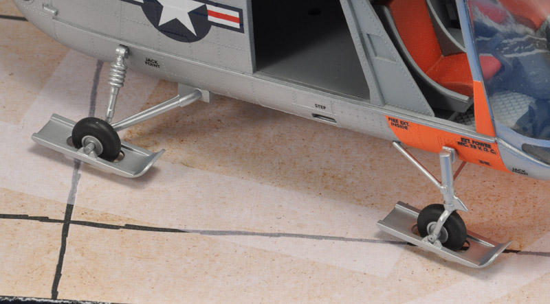
The landing gears were almost last to be added. They were quite laborious to install.
The wheels fit rather wobbly in the front landing gear yokes, and you have to bend the parts considerably. Knowing how brittle the old plastic was, I could not take this risk. I shortened the yokes on the inside, and made a short axle to go inside the wheels. Next I drilled on 0.3 mm hole through all parts, so could install the wheel with a piece of 0.3 mm spring steel wire.
I made complete sub-assemblies of all four gears, painted them MRP-128 Silver, and installed them with epoxy glue. Last to add were the 'snowshoes', and to get them parallel to the ground, I installed them with the model resting on a piece of soft foam, so the wheels could sink in the foam, aligning the snowshoes properly.
| 
|
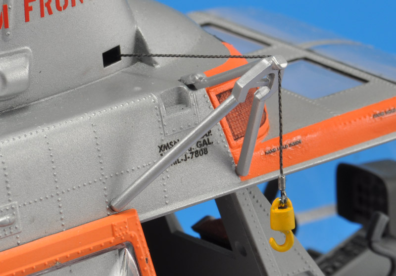
| One but last parts to be assembled were the winch parts. I added a simulated steel cable, made from three strands of copper wire, twisted with my motortool. I added an 0.9 mm Albion micro tubing sleeve over the connection to the hook. A second piece of cable runs from the tripod to an opening in the right-hand rotor pylon.
|
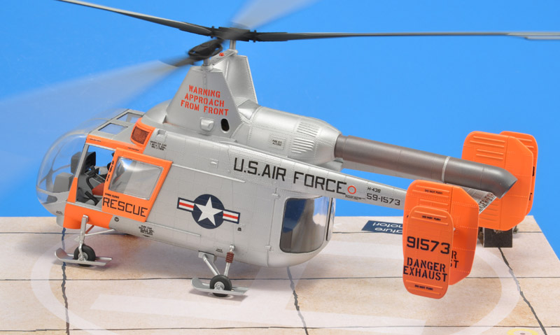
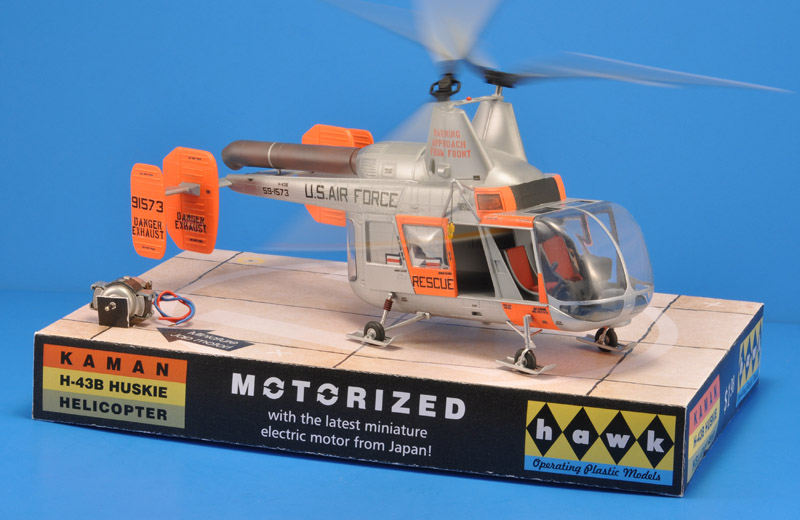
Finished model with shop display
It was a major modeling project for me, but the finished product made me happy. I love the color scheme of this Huskie model! I'm equally happy with the simple shop display, although you probably need to know the original box to appreciate it.
For the fictitious shop displays project, I only used a base, because of the diameter of the turning rotors. For the sides of the base, I copied elements of the 1961 Hawk box. For the top side I used rectangular concrete slabs with tar stripes, reused from my F-84F project. I drew a helicopter 'H-circle' on top of the artwork. Lastly, I made a tiny holder to separately display the original electric motor included in the kit. It was missing in the box I bought, but Paolo 'loupgarou' kindly donated one, many thanks again!
The last element of the display was kindly provided by club member Jan de Jager: he made a Raspberry Pi controller, that made the rotors start and stop every 15 seconds. It worked very well, and gave the viewer an opportunity to study the rotor mechanism at rest. And indeed, the intermeshing rotors made modelers study the mechanism for minutes :-)
|
|
| It felt special to finish a model that had been waiting in its box for probably 50 years or more, went from hand to hand, but got built in the end, in all its glory. I think it's an amazingly nice model for 1961.
|
| I made all 'finished' photos with the rotors turning. It's not very realistic with no pilots on board, but I wanted to stay close to 'straight out of the box'. I only changed the motor, added a bit of rear cabin floor, and added a winch cable, and used my own decals. I left out the battery box.
| 
|
| The model was the centerpiece of our club's display at Euro Scale Modeling 2023. Not because it's the best, but because the turning rotors require more room than the other displays that are stationary, and that extra room was only available in the middle of the club display. The battery pack lasted for the whole day, and the un-lubricated rotor axles did not bind.
|
| The video shows that it will slowly start, run for 15 seconds, and slowly come to a stop. And repeat that cycle indefinitely. It allows more study of the rotor system.
|
|
Spare kit for sale
I bough the 1998 Testors reissue of this kit as possible spares source, but I did not need any parts. It's therefore for sale. As a bonus, I will throw in the geared mini-motor and the resin-cast pinion, so you can motorize the model like I did. See my For sale or trade & wanted page.
Model links
Links
Appendix 1: Color schemes
Here's an overview of the color schemes, as I understand them. The Hawk decals are for color scheme 2, but I don't really understand how that is possible for a 1961 kit.
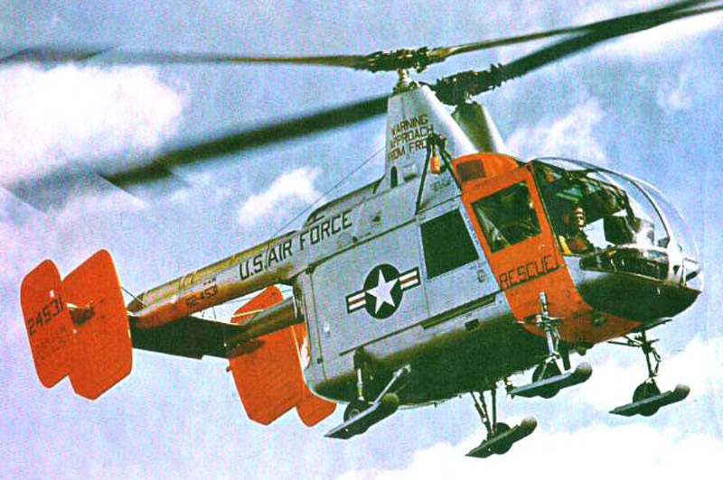
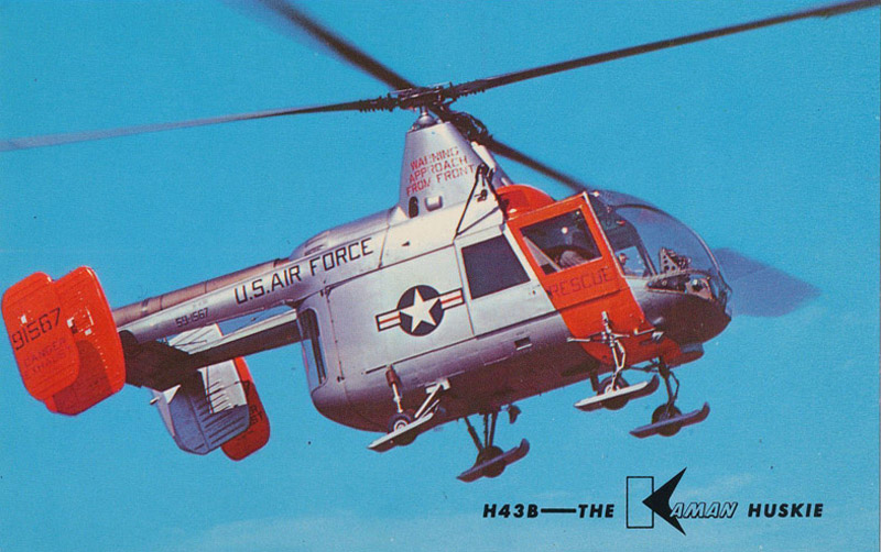
Color scheme 1. Used up to roughly 1963. Silver lacquer overall, large orange areas. Markings in US Navy font. No Star & Bars on top of engine nacelle, and probably none on the belly between the rear wheels. Then called a H-43B, not HH-43B which is a 1962 redesignation. As shown on the Hawk box-art. The 1964 version of TO-1-1-4, page 3.93, shows a largely identical color scheme.
TO-1-1-4 lists 'Code 633' for the 'conspicuity/arctic markings', and according the Dave Klaus' Color Guide, Appendix 4, that's Fluorescent Red-Orange, the FS595 equivalent being 28913. The Fine Scale Modeler article 'Arctic and conspicuity markings', in the March 1996 issue, states: "March 1960, A.F superseded ANA 634 [fluorecent yellow-orange, FS 28915] with ANA 633 fluorescent red-orange (FS 28913). The color faded to yellow-orange after about six months." "Units were told to consume their existing stocks of yellow-orange before requesting red-orange." 'My' Huskie was probably delivered in 1960, being ordered in fiscal year 1959, so it's right on the cusp of ANA 634 versus 633.
| 
|
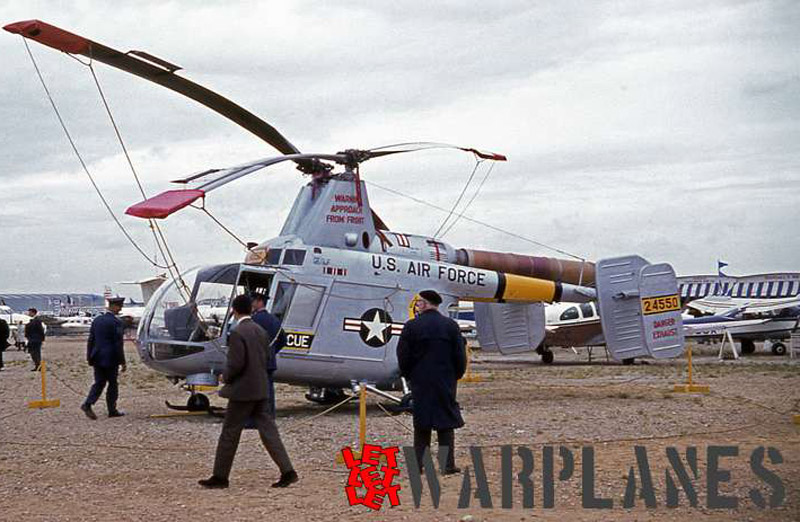
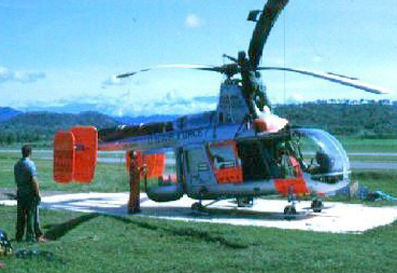
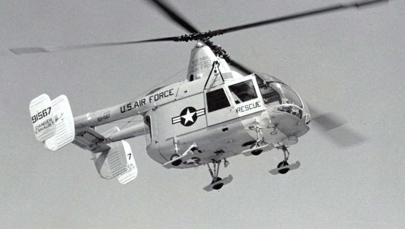
| Color scheme 2. It looks to me like a hybrid (or transitional version) of schemes 1 and 3. I found only a single photo, a 1963 photo of a missile test. Note upper blade color seen on the right. Another one can be seen in 'The Starfighters' from 1964. Similar to Hawk decal sheet and decal instructions. Also shown in TO-1-1-4 from 1964 page 3.93; the yellow band is marked 'ARS only'.
|
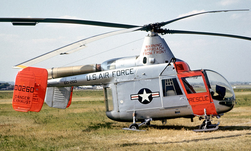
| Color scheme 3. After 1963. Photo is from Le Bourget 1965. Still in silver lacquer I think. All orange areas removed, yellow areas on tailbooms added, serial on yellow rectangle. Star & Bars over engine nacelle. Markings appear to be in USAF font.
| 
|
| Color scheme 4. Somewhere after 1963. Photo is from 1969. ADC Gray replaces silver lacquer, rest the same. MATS badge on rear fuselage.
|
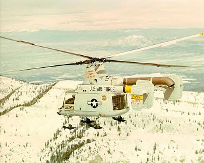
| Color scheme 5. Might come after 1 actually, since markings are still in US Navy font. Photo is made at Bien Hoa 1965. Looks like ADC Gray (or maybe silver lacquer), no orange or yellow areas. Found this quote: The aircraft reportedly arrived at Udorn in their silver 'birthday' suits with bright orange painted on their nose and tails to reflect that they were rescue birds. The old hands at Udorn, Air America crews we understand, took it upon themselves to paint over that orange. We are told none of the crews HH-43 complained. (http://www.talkingproud.us/Military/Pedros/Pedros/PedrosOfftoWar.html)
| 
|
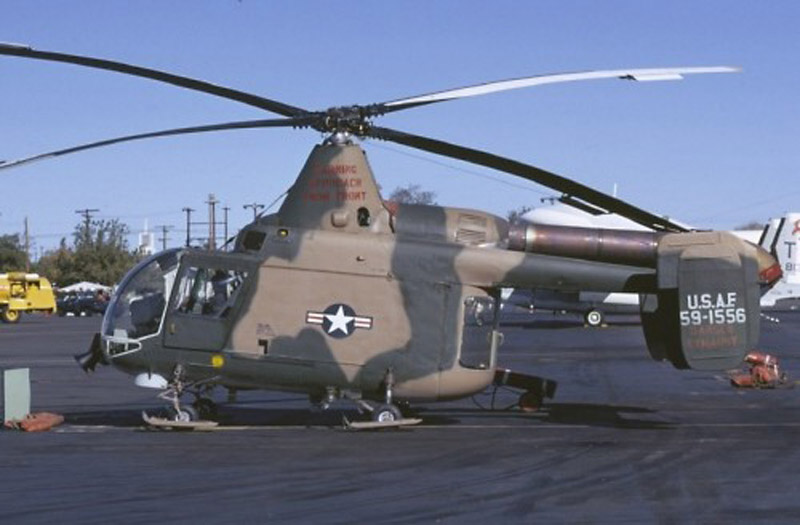
| Color scheme 6. Vietnam use, in SEA camouflage. White serial number. This one appears to have just one instead of two green colors.
|
Appendix 2: Vertical tailplanes of color scheme 1
I checked out all photos of Huskies with color scheme 1, that showed all four fins, and found two painting versions of those fins. It shows that the color scheme of the box art is realistic, and I will copy it.
| Version 1. Inboard and outboard fins painted orange on both sides.
|
|
| Version 1. This Fiscal year 1962 Huskie still has the US Navy style lettering.
|
| Version 1. Picture quality is so bad I can't even read the serial number :-)
| 
|
| Version 2. Inboard fins painted orange on outside only, outboard fins painted orange on both sides. Fiscal year 1960. Kaman was probably responsible for this inconsistency.
|
| Version 2. The orange areas appears very light, probably due to fluorescence. Fiscal year 1959 aircraft.
| 
|
| Version 2. Looks like yellow-orange. Fiscal year 1959.
|
| Version 2. Fiscal year 1959.
| 
|
Appendix 3: Markings
| I wanted to do scheme 1, since I liked the color combination and markings best. Most of the markings looks quite irregular, in a sense that they are not in the USAF-designed font (as presented in Tech Order 1-1-4 for example). It looks more like the Navy font, in being a bit more square with a thinner stroke. But still it's not 100% the same.
|
|
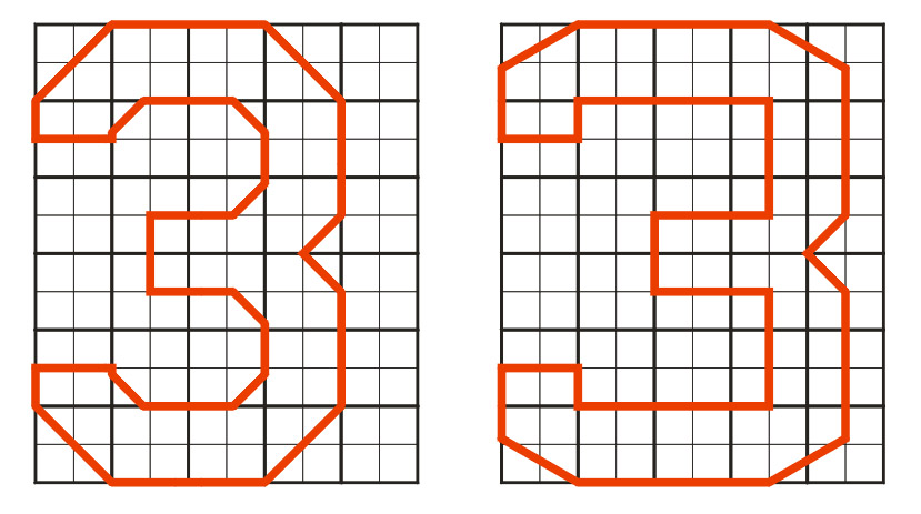
| Here are the USAF and USNavy font for number 3, as an example. The Navy font is wider with a different angle on the corners.
|
| Here are two variations, that I drew to match U-2 serials. The left one has a height-to-width ratio of 6 to 4.5 (like the Navy font) and a radius of half the stroke width. The right one has a height-to-width ratio of 6 to 5 and a radius equal to the stroke width.
| 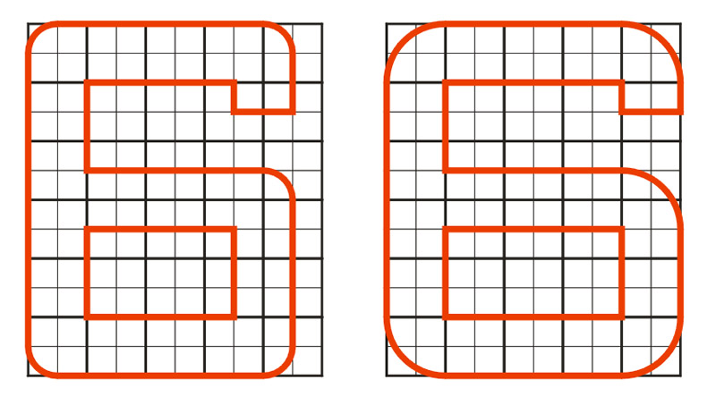
|
| The examples above still had a stroke that looked too fat compared to photos. Therefore I tried a 7 by 5 grid, with radii of half a grid square. That looked quite good.
|
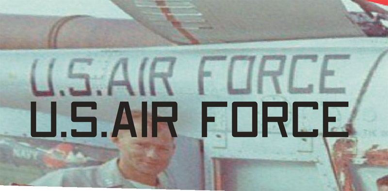
| I took the best photo I found and tried to remove the perspective from the section with the 'U.S. Air Force' text. The width-height ratio is a bit of a guess actually. The 7 by 5 font agrees quite nicely I think.
| 
|
Appendix 4: Serial numbers
Kaman H-43B
58-1841/1860
58-5524
59-1540/1593
60-0251/0292
61-2920/2922
61-2943/2954
62-4507/4565
62-5976/5979
62-12513/12514
63-9710/9717
64-17557/17559
Kaman H-43F
64-14213/14220
64-15097/15103
64-17682
65-10647/10656
65-12755/12758
65-12914/12915
67-14769/14774
Return to models page