Filters can selectively remove or emphasise certain areas in the frequency spectrum. Areas which are removed are named stopbands and areas which are passed are aptly named passbands. If a single frequency is strongly emphasized this is named a resonance, a filter that allows for this resonance is named a resonating filter. On the frontpanel of some synthesizers resonance is also referred to as emphasis or Q. Resonance can be wanted feature, especially when a timbre needs to be dramatically shaped. In other applications it can be an unwanted feature, as an example a strong resonance would not be accepted if it would occur in the bass and treble controls on a hifi amplifier. It is part of the design of a filter if the filter is allowed to resonate on a certain frequency. Some filters can resonate up to the point where they start to oscillate and other filters have no resonance at all. By dynamically changing the resonant frequency extra expressive dynamics in the timbre can be created. Many different types of filters have been developed over the years and all filters that work in the audio range are good candidates to spice up your music.
When a raw oscillator waveform is filtered in a filter module, the filtering will add an extra dimension to the basic timbre of the raw waveform. A common use is to create subtle and natural sounding decays by softly sweeping a filter at low resonance on a static waveform or a sample based sound, using an envelope control signal to control the sweep. Other common uses are to create formant areas in a sound or damp the higher notes a little to make the sound appear more natural or ‘acoustic’. Filters also allow for increased dynamic and expressive playing styles by dynamically tweaking a strongly resonant filter during play. In practice filters are equally important as oscillators in sculpting the timbre of a synthesized sound. Filters are not only used to dramatically alter the timbre of oscillators, but they can be used equally well on virtually any external sound source, like a microphone, a recorded track or looping sample, a drumcomputer, another synth, etc.
In the most traditional approach of subtractive synthesis the oscillator is responsible for the pitch by supplying a pitched waveform which contains all possible harmonics, like the sawtooth waveform. Then, a filter is used to create the formants which are important to create the timbral character of the sound. But if a more complex modulated waveform is fed to the filter the filtering can also be used to emphasize characteristics already present in the waveform. In this case the sound source and the filtering are equally important in shaping the timbre, the oscillator and filter work as a unity to get the desired sonic results. With this approach the range of timbres becomes much greater than with the traditional approach. Remember that what a filter does depends a lot on what is fed into the filter.
There are two common approaches in classifying filters. The first approach is the discrimination between static and dynamic filters. In a static filter the frequency bands are fixed and only the amplitude of each band can be controlled. A good example is the graphic equalizer. This filter basically splits the audio range into a number of bands and for each band the amplitude can be set by a dedicated knob or slider. Another example of a static filter is the bass and treble controls on an amplifier. Dynamic filters additionally offer the possibility to control the frequency range of the band, allowing it to become wider or narrower by knobs and control signals or a digital controlling parameter, e.g. a control signal received through MIDI from a sequencer program.
The second approach is from a totally different angle and much more technical. This approach discriminates between Finite Impulse Response or FIR filters and Infinite Impulse Response or IIR filters. FIR filters offer the possibility of any arbitrary filtering function and are in their practical use quite similar to e.g. graphic equalizers. FIR filters offer much more resolution in defining the filtering curve when compared to IIR filters. The disadvantage of FIR filters is that it is very hard to control them dynamically, a computing device is needed to process a vast amount of controlling parameters into a control array, which can easily hold several thousand filter parameters. This makes FIR filters impractical to dynamically and expressively control a timbre while playing live. In contrast IIR filters are much easier and intuitive to control as they have only very few controlling parameters. So it is this type of filter that is commonly found on sound synthesizers. Resonating filters, where both the resonant frequency and the amount of resonance can be controlled, are in general of the IIR type. The difference in the technical implementation of these two types is that FIR filters are based on a feedforward technique named convolution and IIR filters are based on a feedback technique named recursion. In the chapter on feedforward and feedback you will find more information on these techniques. All references to filters in the rest of this chapter will be to IIR filters.
A filter can at the same time suppress certain frequencies, leave other frequencies basically unaltered and optionally emphasize certain frequencies. This behaviour can be drawn in a graph of the audio spectrum where the curved line indicates the amplitude responses for each possible frequency in the audio range. Such a graph is called the transfer function of the filter and defines the passband characteristics of the filter. There are some typical basic transfer functions for simple filters. If the transfer function reveals that all lower frequencies up to a certain frequency are transferred with virtually unaltered amplitude, but the frequencies above this certain frequency are passed with much lower amplitude, the filter is named a lowpass filter. In practice it will simply pass on all lower frequencies and suppress the higher frequencies. If in contrast the lower frequencies are suppressed and the higher frequencies are passed with unaltered amplitude the filter is named a highpass filter. So, the highpass filter can be seen as the inverse of the lowpass filter. If only a frequency band somewhere in the middle of the audio range is passed unaltered, but both lower and higher frequencies are suppressed, the filter is named a bandpass or bandfilter. A filter can also suppress a band somewhere in the middle of the audio range, making the filter a bandreject or notch filter. A notch is the point in the audio spectrum where a frequency is totally suppressed. The opposite of a notch filter is when all frequencies are passed through, but only one small frequency band is strongly emphasized. Such a filter is named a peak filter or sometimes a resonator as it introduces a strong resonance effect on a certain frequency while the rest of the sound is left unaltered. A similar fiter exists that will pass all frequencies but creates a series of peaks at harmonic intervals, such a filter is named a combfilter. There is also a filter type that does not change the amplitude of any frequency at all but in fact gives each frequency a different phase shift. Such a filter is named an allpass filter.
So, in essence there are seven basic transfer functions, lowpass or LP, highpass or HP, bandpass or BP, bandreject or notch or BR, peak or PK, comb, and allpass or AP. By using several filters with different transfer functions in series and/or in parallel, a combined transfer function can be made that can be much more complex. Such a complex filter can be put to good use to simulate the very complex and expressive timbral changes like those found in spoken words.
Many times the purpose of using filters is to get expressive control over the timbre with the least amount of controls to play with. If the intent is to play live there is probably only a single play controller available like the modwheel, keyboard aftertouch or a foot pedal to control the timbre. Using such a controller puts a limit to the possible complexity of the filter, as only one parameter of the filter can be controlled. An X-Y controller like a joystick allows for some more complexity, as it can control two parameters in a single movement. With a joystick it is for instance possible to control the resonance frequency with on one axis and the resonance amount on the other axis. Or each axis can be used to control a resonance frequency on a complex filter that can resonate on two frequencies. When the synthesizer is controlled from a MIDI sequencer or computer program there is hardly any limit to the complexity of the filtering function, as all parameters may be sent by the sequencer over MIDI, and changing these parameters over time can on most sequencers be edited graphically before the sequence is played.
Learning to play the timbre with the use of filters takes time, just like learning to play any instrument. There is no magical formula that will make a filter instantly sound good. Instead one needs to develop a feel for tweaking filters, to master both the dramatic and the very subtle changes in timbre that filters can produce.
Most prepatched analog synthesizers are equipped with a single lowpass filter per voice. Such a filter will have a control knob for the frequency from where the suppressing of the high frequencies will start. This point is named the cutoff frequency. A lowpass filter on a modular system will also have one or more inputs to enter a control voltage or a control value to initially set or modulate the cutoff frequency. This input can be controlled by e.g. the output of an envelope generator module. This envelope will define how the timbre changes while the note sounds, creating a faster or slower swell and a faster or slower decay. The cutoff frequency control is also a very good candidate to be played by the modwheel or by the keyboard velocity value. Adding just a bit of keyboard velocity control signal to the cutoff will make the sound slightly brighter when hitting the key harder, which can give a more natural effect to the amplitude dynamics of the sound. Another common application is to add some signal from a very low frequency triangle waveform oscillator to the cutoff control signal. This makes the timbre slowly evolve, commonly used to give a ‘sense of going somewhere’ to a repetitive sequence of notes.
The cutoff frequency can also be controlled by a signal in the audio range, a technique that can create exiting new timbres. An example is to do this modulation with a waveform at half the pitch of the played note. This will create a subtle ‘subharmonic effect’ to the sound, giving the timbre a bit more ‘beef’. It is common that this ‘suboctave’ modulating waveform has a tight relation with the oscillator signal that is filtered. However, by having a slightly detuned relation interesting beatings in the sound might occur that can work out very well on long droning sounds. In fact there are many more modulation possibilities for the cutoff frequency and it is great fun to think of new ones, to try them out and see how it can spice up your music.
For many keyboard sounds the cutoff frequency of a lowpass filter needs to be raised if higher notes are played on the keyboard. By default filters are patched in a way that will make this happen by automatically adding some of the keyboard voltage value to the filter cutoff parameter. This is named filter keyboard tracking. It is quite important to have some control on this keyboard tracking. If the tracking is off, meaning that the filter cutoff is set to a fixed frequency regardless of the played note, the highest notes will be heavily suppressed by the filter and can hardly be heard anymore. But if the cutoff frequency tracks the keyboard fully the timbre will in many cases become unnaturally bright for the highest notes. In practice the keyboard tracking needs to be adjusted somewhere between no tracking and full tracking to get the most natural brightness changes when playing notes all over the keyboard. Adjustment is best done by ear to get the most natural feel. Tracking is mostly expressed in a percentage where 0% means no tracking , 100% full tracking and 200% means strongly exaggerated overtracking. A good way to set the tracking is to set an initial tracking percentage of about 30% to 50%, then play a note in the middle of the keyboard and tweak the cutoff frequency for the right sounding timbre for that note. Then play the highest and lowest notes from the melody to be played and adjust the tracking and possibly the cutoff frequency on that middle note again to get the filter to sound just right over the whole keyboard range.
The type of lowpass filter that is commonly found in sound synthesizers offers the possibility to strongly emphasize the frequencies on and just around the cutoff frequency. The knob to control the strength of this effect is commonly referred to as resonance, Q, quality or emphasis, depending on the brand of synthesizer. Opening this knob causes the effect of a very strong resonance at the cutoff frequency and in practice this creates a strong ‘whistling’ formant in the sound. Earlier it was decribed that formants are narrow frequency bands in natural sounds where the frequencies have a much higher amplitude than in other parts of the audio range. Particularly the formants in the range between 500 Hz and 4kHz will strongly characterize a sound. In the real world formants are created by complex resonances in an acoustic musical instrument or in the vocal tract in human speech. The pure sawtooth wave, square wave, triangle wave and sine wave have no formants as in the harmonic spectrum plot of these waveforms all harmonics become gradually weaker when their harmonic number becomes higher. All waveshaping manipulations on these standard waveforms will alter their harmonic content and thus create a weaker or stronger structure of formants, depending on the type of waveshaping used. This formant stucture can be further enhanced by the filter resonance, meaning that here the resonance control on the filter is mainly used to increase the character of the timbre. In general only a moderate amount of resonance will do that job. Of course character is very subjective and a matter of personal taste, so adjustments are best done by ear. As the resonance frequency is the same as the cutoff frequency it is again very important to tweak the keyboard tracking to a percentage that best suits the sound.
The resonance needs to be activated by an impulse in the waveform, it needs to be excited. The abbreviation IIR actually refers to how the filter responds to an impulse, ‘infinite’ in IIR means that the resonance of an IIR filter can be set to a point where it responds infinitely to an impulse. This point is when the resonance knob is about fully open and the filter starts to oscillate and produce a sinewave all by itself. This is named filter selfoscillation. So, by gradually opening the resonance knob the filter starts to respond to impulses by producing increasing amounts of resonance at the cutoff frequency, until the filter starts to oscillate. Before selfoscillation happens the impulses that cause the resonance need to be present in the input waveform. If this waveform has steep edges, like the sawtooth wave and the square and pulse waves, the edges will act as the impulse and a strong resonance effect will result. But waveforms that are very smooth or do not have steep edges, like the sine and triangle waveforms, do not cause much resonance effect at all, even if the resonance knob is set to almost oscillation. Only if there is a strong partial present in the sound at exactly the resonating frequency the resonance will be heard. If the resonant frequency is set to the fundamental frequency of a sound the fundamental will be strongly boosted by the resonance. This is put to good use in bass sounds to create superboom basses. The idea is here to use a highpass filter and set the cutoff frequency on exactly the fundamental frequency. The highpass filter will now pass the signal unaltered, as all that is in the sound to be filtered is in the passband of the highpass filter. When the resonance control is opened the resonance on the fundamental will start to strongly boost the fundamental. The interesting notion about this example is that a highpass filter is used to give more beef to the low end of a sound. So, a highpass filter is not only capable of making a sound thinner, but also to make it more ‘phat’. In the chapter on sound sources it was explained that the flanks in waveforms are named transients and are in fact points in time where the oscillator releases a huge amount of energy. Remember the little experiment descibed at page xx, where a low frequency sawtooth wave was fed directly into a speaker. Let’s do this experiment again, though now by connecting a squarewave oscillator directly to the amplifier. When the frequency of the oscillator is drastically lowered to around two and a half Hz one can clearly hear the rhythmic clicks when the cone is moving in and moving out, and notice the silence between the clicks. Now insert a bandpass filter set to a fairly high resonance setting and a cutoff frequency around 2000 Hz between the squarewave oscillator and the amplifier. Instead of each click a very short burst of a 2000 Hz sinewave can be heard, sounding a bit like claves. Tweaking the resonance knob will make the burst shorter or longer in time. Apply a little bit of the low frequency squarewave to the cutoff modulation input to create an alternating higher and lower pitched clave sound. If you are lucky enough that the low frequency squarewave oscillator has a pulsewidth control you can also change the pulsewidth of the square just a little, to give some swing to the two blips. Lowering the cutoff frequency knob to about 70 Hz will change the sound into what starts to sound like a bassdrum. This is an example of how a simple swinging beat can be patched with only a low frequency oscillator and a resonant filter. But the important thing this experiment reveals is that it is really the flanks in the waveform that excite the filter, and that the resonance is in fact a small burst of a sinewave starting at and caused by the transient. If you now try a triangle waveform instead of the square waveform you will hear how important the flanks really are, as the triangle wave will appear to do nothing at all to the filter. The amount of energy present in the transient directly influences the amplitude of the sine burst. The amount of energy in a transient is determined by the vertical height of the edge in combination with the angle of the transient, the higher and steeper the angle, the more energy it can release in the filter. This explains why the filter resonance does not respond well to a triangle wave, but very well on sawtooth, square and pulse waves. The slope of the triangle wave is simply not steep enough to excite the resonance to make it significant. On the Minimoog synthesizer there is a waveform present that strongly resembles a triangle wave but at the upper and lower peaks of the wave there is a small transient present. Such a waveform can be created by adding about a fifth of a sawtooth wave or square wave to a triangle wave with the aid of a mixer module. The purpose of this waveform is to be able to have sounds based on the typical mellow sound of the triangle wave but that still allow for just a bit of resonance effect to add a bit more resonance character in the filtered wave.
Steepness is the amount of frequency rolloff in the suppressed frequency band. A lowpass filter with its resonance knob at its lowest value will hardly suppress frequencies around and below the cutoff frequency. When the pitch of the input signal is gradually raised above the cutoff frequency, the input signal gets suppressed more and more. If the amplitude decreases very quickly when the pitch is raised by an octave interval higher as the pitch, the filter is said to have a steeper cutoff slope. This can be tested very well with a sine wave. If the filter cutoff frequency is set to 500 Hz the sinewave will be passed without significant drop in amplitude below 500 Hz. But from 500 Hz up it will gradually decrease in amplitude. The steepness of a filter is expressed in dB per octave or simply dB. dB stands for deciBell and is a relative value. This means that first a reference must be defined and this reference is interpreted as 0 dB. 0 dB is referred to as unity gain when the amplitude of the imput signal is the same as the amplitude of the output signal. With a filter the output amplitude of the sinewave at the cutoff frequency is taken as the 0 dB reference value. Now raise the frequency of the sinewave by an octave. If the amplitude has dropped to half the amplitude at the cutoff point the suppression is said to be –6dB. If the amplitude has dropped to a quarter value the suppression is –12dB. And if it has dropped to an eighth the suppression is –24dB. The filters that would cause these attenuations would be said to have a steepness of respectively 6dB, 12dB or 24dB. Musically a steepness of more than 24 dB is hardly heard and so 24 dB for a lowpass filter is commonly considered as sufficiently steep for timbre shaping purposes. In the last examples a theoretically perfect filter is assumed, in practice the slope starts a little below the cutoff frquency and bends down smoothly before becoming an almost straight line downwards. But this is of little concern to a musician as in the end the sonic effect of a filter on the material that is fed into the filter must be judged by ear.
Technically filters are made by cascading basic filter building blocks that have a fixed 6dB steepness. This is why the steepness of filters is commonly denoted by a multiple of 6dB. These building blocks are sometimes referred to as poles. The word pole is derived from the mathematics involved in designing filters and is not an entirely correct name for the building block itself. The word pole should only be interpreted as an indication on how many building blocks are used, so if a filter is referred to as a 4-pole filter, it indicates the use of four building blocks that can be combined in a number of ways. If combined as a lowpass filter it would indicate a 24 dB filter. But note that this 4-pole filter could also be a variable width bandpass filter with two 12 dB slopes, a bandfilter with a 6 dB highpass and a 18 dB lowpass slope or any other combination that can be made with four of the basic 6 dB highpass, 6 dB lowpass or allpass building blocks that are available to the synthesizer designer. This means that, on the most common synthesizer filters, the steepness is fixed by the architecture chosen by the designer of the filter. But when more filters are present there are a number of tricks to get some control over the steepness and the more interesting ones will be explained later.
Sometimes it is said that the steeper the filter the better the filter. This is not entirely true, it depends a lot on what is actually filtered. The steeper a lowpass filter the more the brightness gets suppressed. Which can be an important argument to use a less steep filter when filtering an audio track, a looping sample or the signal from a drum computer. Preferrably one would like to have several filter types available, all with different steepness and resonance characteristics. Here a modular synth has a distinct advantage over a prepatched synth. On a digital modular synthesizer there is the additional advantage that as many filters as fit in a DSP can be used to create a very complex filter with a very complex transfer function.
Filters can be cascaded in series and used in parallel to create more complex filtering functions. There are some simple cases, like cascading a lowpass filter and a highpass filter to create a variable width bandpass filter. When using filters in parallel and by mixing their outputs together with a mixer module, they start to interact in an interesting way. In a filter each frequency will be shifted in phase a little. The phaseshift for a certain frequency on the outputs of two parallel filters will be different if the filters are set to different cutoff frequencies. When the outputs of the two filters are mixed the phase shifts will cause an extra cancellation and emphasis of certain frequencies. There are filter types that specifically use this effect, these filters are commonly named elliptic or Cauer filters. These filter types can be easily created by combining two or more filters in parallel, feeding them the same input signal and adding or subtracting their outputs from each other in a mixer. If this is done with two resonant filters there is the additional bonus of two resonant peaks, effectively creating two possible formants in the filtered timbre. This can give the sounds a musically interesting ‘talkative’ character.
These filters are more or less the basic building blocks all other filters are made with. The filtering effect is soft without significant coloration and these filters are very useful when only a shallow frequency rolloff is necessary. Resonance is not possible with these filters. An important characteristic of these filters is that their gain in the passband is slightly less than unity gain. This makes the 6dB lowpass filter ideal to be used in a feedback path in echo delay lines, selfmodulating FM oscallators and waveguide oscillators to create high frequency damping and to prevent feedback oscillation to occur. The phaseshift of these 6 dB filters varies for each partial in the input signal and is around 45 degrees at the cutoff frequency.
These types are not very useful in colouring the timbre of a sound, as their filtering action appears shallow and doesn’t add any significant character of its own. Still, they are quite important as they can be used for all sorts of other useful purposes. The 6 dB highpass has the important property that it blocks DC components in audio signals, used this way it works the same as an AC-coupling capacitor in analog circuitry. This can be put to good use in digital systems, as there are synthesis methods where an inherent DC component is added to the generated waveform signal. If such a signal is applied in a feedback loop it can lead to a build up of the DC component, which will shift the audio signal towards the positive or negative clipping border and create unwanted clipping. Passing the audio signal through a 6 dB filter set to a low frequency around 40 Hz will remove any DC component and cure this unwanted clipping. There is one drawback and that is that a 6 dB HP filter does not allow for a feedback greater than one or unity gain, as this will cause a radio frequency oscillation on an analog filter or an oscillation at half the sample rate on a digital HP filter. If deep feedback is desirable, like in some types of digital FM synthesis, it is advisable to also enter a lowpass filter in the feedback loop set to a frequency of around 1/8th of the system sample rate to prevent unwanted oscillations of the feedback loop at half the sample rate. Another situation where a 6dB highpass filter can do wonders is when a kickdrum and a bassline conflict with each other and make the low in a mix sound muddy. By routing either the kick or the bass through a 6 dB highpass filter set to around 80 Hz to 150 Hz the mix can be improved. Judgement by ear is again important here. And when a microphone signal is fed directly into a synthesizer, e.g. to do vocoding or another type of speech mangling, routing the microphone signal through a 6 dB highpass set at around 150 Hz will fight rumbling sounds in the microphone signal and too much low end in a vocoded signal.
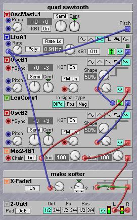
6 dB filters are not commonly found on commercial analog modular synthesizers. But they are commonly found on FX machines that have reconfigurable signal routing and on digital modular synthesizers. On DSP-based modular synthesizers a 6 dB lowpass filter can be easily make with a simple two input mixer, which was earlier explained in the chapter on feedforward and feedback at page xx. To summarize the principle; when the output of the mixer is routed back to one of its inputs there will always be a one sample delay as the feedback input will calculate with the value of the last time the output was calculated. Such a circuit is named an integrator. The one sample delay is sometimes referred to as a Z-1 function. This small delay is essential in building digital filters, it provides for a small time delay that is essential in the filtering function. In this example of a simple ‘two input mixer integrator’ the mix on the two inputs must be balanced, if the feedback is increased the input signal on the other input must be decreased in an equal amount, if feedback is 75% then the input signal must be attenuated to 25%. This means that a crossfade mixer in a linear mode will do this job perfectly and with only one knob. The actual cutoff can be calculated, but the formula is a bit complex. Instead it is better to tune this little ‘do it yourself’ filter by ear. In analog circuitry the same idea is used, but done by connecting a small capacitor over an inverting opamp. This simple soft filtering trick can be applied on the output of a sawtooth waveform oscillator to make the oscillator appear to have a warmer sound. Especially on unison sawtooth sounds this can increase the sense of depth in the sound. A nice side effect is that if a high resonance filter is used on this unison sound the resonance in the very high is dampened, which gives a much more analog sound and a more balanced filtersweep on a digital system.
The 6 dB allpass filter will pass all frequencies equally well. When an audio signal is fed into the allpass filter it appears like nothing happens. So, why on earth would one want to use an allpass filter when it doesn’t filter away anything? The answer lies in the fact that the filter actually does something dramatic, but this can only be heard if the allpass filter is used in combination with other modules. What an allpass filter does is shift each partial in a sound in time. The timeshift is only very little and related to the wavelength of the waveform. In fact it is between virtually no time shift for the low pitched partials to almost half of the partials waveform period for high pitched partials.
The idea to make an allpass filter is simple. First a signal is filtered with a 6 dB lowpass filter. Then the lowpass filter output is subtracted from the lowpass filter input, which will regain what the lowpass filter threw away, effectively creating an extra highpass filter output. If these lowpass and highpass outputs would be added together again it would give an exact replica of the input signal. But before being added together the highpass output is reversed in phase.This means that low pitched partials remain virtually unchanged, but very high pitched partials will be almost reversed in phase. Still all partials will pass the filter. The 6 dB slope of the lowpass filter will take care that partials pitched in the mid range will have a phase shift somewhere in between, in fact a partial that is at exactly the cutoff frequency of the lowpass filter will have a phaseshift of exactly 90 degrees. When the phase shift is plotted in a spectral plot it will show a gradually smooth curve.
A common use for allpass filters is to put several in series, eight to twelve is common, and mix the output with the original input signal. As phase shifts accumulate in the chain of allpass filters there will be several frequencies where partials are in opposite phase and these will cancel out each other, while at some other frequencies partials will be in phase and come out at double the amplitude. This is the principle of a phaser module. By creating an extra feedback path from the output mix back to the beginning of the allpass filter chain the whole chain can be made resonant as well. By slowly sweeping the frequencies of the allpass filters a typical swooshy phaser sound is generated.
Another use for allpass filters is in the feedback path of echo delaylines. What the allpass filter does is mimic the behaviour of the coils in the recording and playback heads of a tape echo device. In general these heads were not of the most expensive type and together with the capacitive coupling with the rest of the electronic circuitry the heads would act like allpass filters. The effect is that when an echo repeats every repeat is slightly different which results in a much more natural timbral change in the decaying echoes as e.g. a straight digital delay that only uses a lowpass filter. So, when using an allpass filter in the echo repeat feedback path of a digital delay it will sound more natural. It is a bit like the echoing in a room where the walls are not exactly at ninety degree angles or that has reflective surfaces on furniture that is irregularly placed in the echo room.
Allpass filters can also be used to create filter slopes that have different slopes as multiples of 6 dB. Another use can be in RIAA correction filters used for cutting and playing back vinyl records. This RIAA correction filter has an almost straight 6 dB slope over the whole audio range.
In general allpass filters can be used to create specific effects where different phase shifts of partials will cause specific effects to happen in surrounding circuitry. E.g. allpass filters can be used to make a filter that will create pink noise from white noise, where the filter must have a virtually straight -3 dB slope. Such a filter is also useful to emulate the damping action of humid air on a sound that comes from some distance, a reason why allpass filter are also used in complex reverberation algorithms that take air dampness into account. Many digital synthesizers have a flat spectrum, comparable to a flat white noise spectrum. A filter that can tilt the whole spectrum can filter these digital synths in a way that their audio spectrum tilts down towards the high end with e.g 1 to 3 dB per octave. This will greatly enhance the spatiality in chorus sounds without creating the sense that the high end is filtered. There is a good psychoacoustic reason why this works, which has to do with how the two mechanisms that define sense of direction in the mind work. One of these mechanisms works below roughly 3.5 kHz and uses time delays and amplitude differences between the two ears, the other mechanism works above this 3.5 kHz and uses the combfiltering effect of the pinnae of the ear, the reason why it is possible to pinpoint the direction of a sound with only one ear. Just a little turning of the head will immediately give the correct sense of the direction of the sound, as long as it has some partials above 3.5 kHz. The human mind expects a certain balance in volume for the two audio ranges these two mechanisms work in, as the mind combines information from both mechanisms in defining the direction of a sound. If the volume balance is not like how it is expected from sounds in nature the mind gets confused and actually starts to refuse to generate a sense of direction at all. E.g. pink noise creates a strong sense of spatiality, but white noise does not. So, to make the spectrum of a digital synth more like the pink noise spectrum will in fact enhance spatial chorused and reverberated sounds. Analog synths are less perfect as digital synths and need less treatment or no treatment at all. In general these corrections are made when an experienced mastering engineer is making a master mix. But only few can afford the services of a really good mastering engineer, so it is good to know about these psychoacoustic principles and being able to make these corrections oneself. Conclusion is that the apparently lowly allpass filter is in many cases exactly the main secret in what makes the difference between something that sounds and something that sounds good and agreeable, and isn’t lowly at all.
This type of filter has three simultanious outputs; a 12 dB lowpass output, a 6dB bandpass output and a 12 dB highpass output, which makes it a very versatile filter. This filter will basically split the audio range into three different bands. It allows for resonance on all three outputs, the amount of resonance can be set by a resonance knob. The internal architecture of the filter is quite simple, two 6 dB building blocks are used in series and are fed back with an inverted signal. If the feedback is exactly unity gain and the filter is exited with a small pulse it will start to oscillate on the cutoff frequency and oscillate forever. By allowing for slightly more feedback than unity gain the filter will in fact turn into a sinewave oscillator. This amount of feedback is set in the filter design itself, so the designer of the filter can define if the filter will allow for oscillation or not. To reduce the resonance, the signal at the point between the two filter building blocks is used as a second feedback signal. Which means that this filter type actually has two feedback paths that control its resonance behaviour, one fixed to set the maximum amount of resonance and a variable one that in fact reduces the resonance. The three outputs are taken from the points in the circuit after the two building blocks and after the inverted feedback point. The filter is cheap to build and not very critical. It is found on many of the cheaper analog monosynths from the eighties. The slope of 12 dB on the lowpass output gives reasonable filtering action but is not steep enough for all applications. In contrast the resonance can be very pronounced with a slightly whistling character. This makes it a filter that is a bit difficult to work with from a sonic point of view, it needs careful tweaking. The true power of this filter is in how the three outputs can be combined to create a huge range of filtering effects that are simply not available on other filters, but most of these effects are subtle. In general the filtering effect is not strong enough to be the module that is solely responsible for shaping the timbre, still it is very useful in combination with a waveshaping technique that does its part of the timbre shaping.
Combining the three output signals in a mixer creates a whole range of possible filtering functions. Mixing equal or differing amounts of the high and low outputs allows for a filtering curve with a deep notch. When the amounts of highpass and lowpass output signal are exactly equal, the notch will be at the cutoff frequency and the resonance knob will have not much audible effect anymore. This is because the resonance peak at the HP output is phase reversed to the resonance peak at the LP output, which suppresses the resonance fully when these two outputs are mixed equally. If the amounts of LP and HP are unequal the filter has an elliptic response, which also has a notch but not at the resonance point. Also, so some resonance will reappear. If there is more lowpass signal the resonance frequency will be lower than the notch frequency and when there is more highpass signal the resonance frequency will be higher than the notch frequency. By subtracting the highpass output from the lowpass output all audio is passed through, but a strong resonant peak can be created if the resonance is raised, creating a peak filter. This is because the subtraction will phase reverse one of the outputs, bringing the resonance peaks on the outputs in phase again. Subtraction is simply done by mixing the lowpass output with the phase reversed or inverted highpass output. This will need either an inverter module or a mixer which can invert its inputs.
The following filter curves are possible when mixing the three outputs of the filter in certain amounts:
|
Type |
Amount of LP |
Amount of BP |
Amount of HP |
|---|---|---|---|
|
12 dB LP |
100% or 0 dB |
- |
- |
|
6 dB LP |
100% or 0 dB |
100% or 0 dB |
- |
|
6 dB BP |
- |
100% or 0 dB |
- |
|
6 dB HP |
|
100% or 0 dB |
100% or 0 dB |
|
12 dB HP |
- |
- |
100% or 0 dB |
|
Notch filter |
100% or 0 dB |
- |
100% |
|
Elliptic LP |
100% or 0 dB |
- |
0% <-> 100% |
|
Elliptic HP |
0% <-> 100% |
- |
100% or 0 dB |
|
Peak filter |
100% or 0 dB |
- |
-100% or inverted phase |
|
Phase inverted peak filter |
-100% or inverted phase |
- |
100% or 0 dB |
|
Allpass filter |
100% or 0 dB |
100% or 0 dB |
100% or 0 dB |
The elliptical modes are useful for subtle filterings where a certain frequency needs to be removed or emphasized. In the case of an elliptic LP mode the cutoff can initially be set to a certain frequency and then by opening the HP mixer control the notch is created. The notch is swept in from very high at 1% HP signal to the cutoff frequency at equal amounts of LP and HP signal. If the notch is set to about an octave above the cutoff frequency the filter sounds steeper than when only the 12 dB output is used. Somehow this elliptic mode seems to sound best when the notch is on a relatively higher frequency when the cutoff frequency is low, when raising the cutoff frequency the notch should get closer to the cutoff frequency. To get this effect the amount of HP mix will depend on the cutoff frequency, but not with a simple formula. So, adjustment is best done by ear. Another effect of mixing in a bit of the HP output is that the resonance gets slightly reduced until it disappears at an equal mix of LP and HP output, which was explained on the previous page. Together with what appears to be a steeper slope due to the notch, this reduced resonance effect can subtly change the sound of the filter. This filter mode works well on rich and bright input signals, like thick and bright unison string sounds and on the cymbals in drumloops. Slow modulation of the cutoff can give e.g. a static drumloop a much more lively character.
There is quite a lot of phaseshift of all the frequency components in the output signal in respect to the input signal. This effect can greatly add to the apparent warmth of the sound when the filter cutoff is swept. The more the filter is set to an elliptic mode, the more the effect of phase shifting becomes apparent. The very subtle phasing effect this creates can give some nice warmth to the sound. However, this might be less desirable when filtering external audio sources, like recorded tracks with vocals, but again it can be a great effect on drumloops.
When the resonance is set to selfoscillation the sinus waveforms on the outputs have a phaseshift of 90 degrees for the bandpass output and 180 degrees for the highpass output in reference to the signal at the lowpass output. When additionally the bandpass output is inverted there are four sinewave signals available with respective phaseshifts of 0, 90, 180 and 270 degrees. Most 12 dB filters can resonate at very low frequencies if the cutoff is set to its lowest value and additionally a negative control value is patched to the frequency control input. When these signals at these very low frequencies are fed to the control inputs of four VCAs that feed four amplifiers and speakers, a sound that is fed into all VCA inputs can be made to rotate quadraphonically around the four speakers.
An additional feature of the 12 dB filter is that some part of the LP output signal can be fed back to the filter input. This will slightly boost the lower frequencies giving the sound more ‘beef’. However, this will also offset the two basic filter elements (the poles) used in the 12 dB filter which slightly changes the cutoff frequency and reduces the resonance. This will make the filter sound closer to a pure analog filter, as the filter elements in analog filters are never the same due to component tolerances. About –12 dB seems a good value to make the filter sound warmer and the resonance slightly less whistling. When increasing the feedback to about –1.5 dB the filter will start to sound distinctly different, often a thick and fat sound with a slight distortive character will result. But this can quickly make a timbre sound ‘muddy’, so careful adjustment by ear is again necessary.
The peak filter is a special case. If there is no resonance the peakfilter acts as a simple allpass filter without much audible filtering effect. But when the resonance is raised to a fairly high value a strong resonant peak is introduced that can be swept through the audio range. This can be very useful to breath some more life in sounds from drum computers and sampled loops. On the G2 the peak mode is already pre-wired in the 12dB multimode filter. It can be used by setting the filter to the 6dB mode and using the bandpass output. With this setting the bandpass output is actually an allpass filter with a resonance peak when the resonance control is opened.
Another interesting variation is to put a few 12 dB filters in parallel and use the bandpass outputs to create a fixed or controllable resonant structure with several resonance peaks. By simply mixing the outputs of three such filters in a 3-input mixer, the ‘formant filter’ module of some vintage analog modular synths can be conveniently recreated with about the same DSP-resources as needed for a single 24 dB filter. A crossfader can be used to crossfade between the input signal that goes into the filters and the output of the mixer than mixes the BP signals to control the depth of the effect.
Strongly resonating bandpass filters are often used in a synthesis technique named modal synthesis. With this technique a number of bandpass filters are excited with one single pulse, causing them to ring for some time. When these bandpass filters are each tuned to a partial in the sound to be synthesized, quite convincing emulations of certain groups of acoustic instruments can be created. It is important to have very detailed control over the ringing time. An extra degree of fine tuning for the resonance can be accomplished by feeding back a phase reversed portion of the bandpass output to the filter input with an extra mixer module at the input, while the resonance of the filter is set to maximum. If the mixer used uses exponential control the ringing time of the filter can be set more precisely by careful adjustment of the feedback mixer knob.
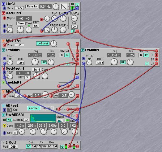
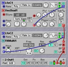
Another interesting filter variation is to use only the LP outputs of two parallel 12 dB filters, invert one of the outputs and mix them together in a mixer. In this configuration, either the resonance settings must be kept equal on both filters or the Gain Control must be set to off (GC button). When the Gain Control is off there should be an extra signal attenuator before the inputs of both filters, to prevent possible clipping on high resonance settings. If the mixed output signal amounts are equal and the non-inverted filter is set to a higher cutoff frequency a bandpass filter is created, as only the band between the two cutoff frequencies is passed. This can be explained by imagining that the output signal from the lower tuned filter is also present in the output of the higher tuned filter, so by subtracting the output of the lower tuned filter from the output of the higher tuned filter only the difference between the two output signals is left, and that is the band between the cutoff frequencies of the two filters. This bandpass filter has two slopes of 12 dB and can be set to a variable width by control of the respective cutoff frequencies. By raising the resonance of the filters two resonance peaks will appear at the corners of the band. A filter with a variable bandwidth can be a great tool to mangle vocals, creating telephone sounds, etc.
A variation on this filter is when the lower tuned filter output is controllable in level by a knob. This will create a filter that is smoothly controllable between a lowpass filter and a variable width bandpass filter. Instead of controlling the amplitude of the lower tuned filter the higher tuned filter can be controlled. This creates a filter with a controllable slope between lowpass and variable width bandpass, but it will go through a range halfway where the filter combination is in elliptic mode. Especially this last mode is interesting as it can make the filter appear more steep when the higher tuned filter is tuned to about a half octave above the other filter and its output is at a value somewhere around –6 dB. By carefully listening while adjusting the level the effect on the slope can be heard very well and tuned to a sound you like. When the higher tuned filter is tuned to some two to four octaves higher the filter combination will appear to have more ‘spit’, again adjustment is best by ear. Important is that the resonance settings on both filters should be exactly the same, as this gives the most interesting timbre shaping ranges for this filter combination. Whenever one of the filters is retuned the level knob of the highest tuned filter should be adjusted as well. This parallel combination is more interesting as putting two filters in series to get a steeper filter. The sonic difference between paralllel and serial becomes clearer when the resonance is raised to a fairly high level. In paralllel mode both resonant peaks come out much better in the mix and have more timbre shaping power, which makes the filtered sound more interesting.
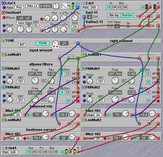
Many times it is necessary to have a simple control over the tonal presence of a sound. Presence of a sound in a mix does not only depend on its volume, but also on the overall tonal balance. Digital sounds often have too much energy in the very high of the spectrum. Using just a LP cutoff filter to temper the high is not enough. What works much better is to give the sound the same kind of filtering that is used to filter pink noise from white noise. This means that the whole sound spectrum should be tilted by a staight line. When using two 12dB filters in allpass mode this straight downsloping curve can be approximated sufficiently to create just the right amount of psychoacoustic tone filtering to increase the apparent presence of a sound. The idea is that two allpass filters are tuned about a decade apart, around 200 Hz and 2000 Hz are good values. The outputs are added together in a fixed balance and this sum is either added to or subtracted from the input signal by a controllable amount. The frequency dependent phase shifts caused by the allpass filters will cause the specific slope when it is combined with the input signal. The only disadvantage is that there is some changes in overall outputs level, but with a simple trick these can be corrected for. The result is a tone control with one single knob that corrects the loudness levels in the frequency bands in a way that the attention will shift to e.g. the melodic parts of the signal. And it is exactly this shift of attention that improves the presence of the instrument in the mix. This filtering is very useful to give digital instruments a warmer sound, but can also be used to either boost the bass or boost the extremely high end of the spectrum.
A very interesting property of the state variable filter is that it can be designed in a way that it does not have three outputs but has one output and three inputs. From one input only the low part of the spectrum will be passed through, another input will only pas a small band and the third output passes only the high part from its input signal. In this particular design the filter can act as a spectral crossfader between two different input signals. An example is when a drumloop is fed into the LP input and another drumploop is fed into the HP input. This will result in a mix that has the low drums from one loop and the high cymbals from the other. By turning the frequency cutoff knob fully from one side to the other there will be a crossfade from one drumloop through the other, fading in one signal from the low while the other signal is pushed away into the high. There has been only one commercial instance of this filter made by Modcam and designed by Nyle Steiner, who is also known for inventing the Steinerphone, and electronic windinstrument that would later become the Akai EVI windinstrument. In the next chapter, that is all about building your own filters with simple filter building blocks, an example of a spectral crossfader patch based on a G2 24dB filter patch will be given.
This type of filter was invented by Robert Moog in the early sixties and used on all the Moog synthesizers. The filtering action is quite pronounced and it has a very nice sounding resonance. The most peculiar thing about this filter is that when it is used on an unisono sawtooth sound created with e.g. three slightly detuned sawtooth oscillators, it tends to give the sound a distant spacial character. It is particular the sawtooth waveform that has this effect, when using pulsewidth modulated waveforms the reverberant character seems to disappear and the sound sounds much closer. As the effect of the filter on sawtooth waves is experienced as very beautiful by most listeners, the filter has gained an almost legendary status amongst musicians. The filter is perfect to create lush padsounds and roaring basssounds as it has a great timbral shaping effect in this sort of application. Technically, the filter is designed as two symmetric cascades of four transistors with capacitors between the transistors. By driving a variable current through the transitor cascades the cutoff frequency of the filter is controlled. The filter needs exactly the same type of exp/lin converter as an analog oscillator to be controlled. The filter has gained its nickname ladderfilter from the schematic of the filter circuitry, where the two transistor cascades look a bit like a ladder. The Moog filter was patented by Moog around 1965 and for a long time other manufacturers could not use the design. At the moment when the design could be used by others, chips had become common and 24 dB filters were made with voltage controllable operational amplifiers in a chip. One of the last synths that was equipped with a true ladder filter was the Roland TB303, although Roland made a little change in the design. This design change gives the TB303 filter a completely different, much more agressive sound, with a lot more spit when compared to a Moog filter. The TB303 was initially a marketing failure, but years after production was ceased it suddenly became very popular in Techno music styles. This caused many synth manufacturers in the nineties to suddenly started building TB303 clones, some with the ladder filter as made by Moog and others with the TB303 modification.
At the end of the seventies two chipmanufacturers started to produce complete 24 dB filters in a single chip solution, Solid state Music and Curtis Electromusic Specialties. The chips made by these manufacturers have been used extensively in the analog polyphonic synthesizers of the eighties. Production of these chips has long ceased, but their sound remains in the massive amount of analog polysynths still in operation today. These days manufacturers of analog modular synths tend to use standard components again, simply as it is hard to get hold of a bunch of these chips from the eighties.
24 dB filters can be emulated very well digitally and manufacturers of digital modular synthesizers have a choice of how to program filters and what their qualities should be. It is hard to say something in general about these digital implementations, as each manufacturer seems to use one of their own little tricks to give their filters a good sound. Musicians in general tend to think that digital filters sound less warm than analog filters. This can be partly explained by the fact that the signal from digital oscillators tends to be brighter than that of analog oscillators. Additionally, analog circuitry can have small nonlinearities, which cause a little harmonic distortion which slightly colorates the timbre. The issue is very subjective and in general it doesn’t really make much difference in a final mix, as long as the mix itself sounds good. In practice digital filters do a very good job and have the additional advantage that, because of their exactness, combinations of filters can be made that are very difficult to do on analog modular synthesizers, unless the analog filters are really top quality.
All 24 dB filters work very well with the earlier descibed exciter/resonator synthesis model. When resonance is set to a medium to fairly high level the flanks in sawtooth and pulse waveforms create very nice resonance effects. It is not uncommon to add a little saturation distortion after the filter, to create some extra character. In general the 24 dB filter is easy to tweak as it basically does only lowpass and resonance. But small changes in the cutoff frequency can have quite an effect, because the filter cutoff slope is steep. So, it is important to tweak the filter carefully while listening well to the minute effects, especially when additional saturation is applied.
The four audio inputs on the Nord Modular G2 can be put to good use to process all sorts of audio material, like sampled loops, drumcomputers, audio from a computer, etc. The way audio processing modules can be freely patched in any order makes the G2 an ideal EFX machine. There are three basic types of audio processing available on the G2; filterings, distortions and time displacement effects. Filterings and distortions are used to lively up static samples or give sounds more beef. Time displacement effects are all effects where a time delay of the audio is used to create a special effect, like echo delays, reverbs, flangers, etc. Due to the modular nature of the G2 all three types of audio processing can easily and conveniently be combined to allow for a virtually unlimited range of effects. It is also possible to extract control signals from audio, examples are the loudness contour and a signal that can make an oscillator track the pitch of an incoming monophonic signal.
Filtering can be an effect in itself, but it can also be put to very good use to support other effects in a subtle way. As when processing audio it is many times needed to first filter parts of the sound, with the purpose to have an effect in only a selected part of the audio range. A common example is to have a distortion effect work only in the lower or middle range and not on the higher frequencies, with the purpose of giving this distortion a warmer and grungy effect.
The exactness of digital filters allows them to be used to do ‘arithmetic’ with the passbands. Remember that when the 12 dB filter was descibed it was explained how a variable bandwidth bandpass filter could be made by subtracting the output of one filter from the output of another filter. This can be done equally well using 6dB to 36dB non resonant filters and resonant filters that are set to exactly the same resonance setting. The first possibility here is to create a crossover filter. Such a filter splits the audio spectrum into two bands, and when these two bands are added together again the exact same sound should return. If the output of a lowpass filter is subtracted from the input signal, the part that is thrown away by the filter is regained from the input again. This signal will basically be a highpass signal, although the cutoff slope of this highpass signal is not equal to the cutoff slope of a proper highpass filter. So, if the lowpass filter is 24 dB the regained high will not have a low frequency rolloff slope of 24 dB. In practice this is not much of a problem, as the mind perceives the effect of a highpass filter in a different way as the effect of a lowpass filter. But our main purpose here is to create two bands that when added together again will recreate exactly the original input signal again.
A common use of crossover filters is to give each frequency band a different effect and then add them together again. A good example is when a thick chorus is applied to a sound, this will make low frequencies muddy and the very high frequencies can become like a high pitched buzz making the sound loose definition and causing conflict with sounds that have by nature a very defined high. In many cases chorus works best if it is applied to the range between 500 Hz and 4 kHz. This is about the range of the ear where the sense of spatial direction takes place. A chorus or unison effect in this frequency range will give a sense of a natural space.
When the spectrum is split into two parts with a crossover filter, one of the bands can again be split by another crossover filter. This way a multiband crossover filter can be made. These kind of filters are commonly used in filterbanks, multiband compressors or multiband special effects.
A typical crossover filter has one input and two or more outputs. When the outputs of a crossover filter are mixed together again, this mix should preferrably give an exact replica of the original signal. This last property is sometimes referred to as phase linearity. There is no dedicated crossover filter on the G2, but making a crossover filter is actually quite easy to do. The basic idea is to recover the high part of a signal that is thrown away by a lowpass filter. This is done by extracting the difference signal between the input and the output of the lowpass filter. Imagine that the ouput of the filter is mixed in reverse phase with the signal that goes into the filter. As the low part of the signal is in reverse phase with the low part of the unfiltered signal, these two parts will be cancelled out in de mixing. But as there is no high part in the filtered signal anymore only the high part of the input signal will be present at the output of the mixer. There is one requirement for this to work properly, and that is that the filter must have a gain of exactly one (be at unity gain) in its lowpass band, so it does actually cancel out exactly in te mixer. Pure analog filters are not precise enough for this use. In fact, crossover filters is an application where digital filters have a definitive advantage over analog filters, as they can have exactly unity gain in the passband. A good filter to use on the G2 is the non-resonant lowpass filter named FltLP. The advantage of this filter is that there can be no possible coloration of the timbre due to resonances in the filter. The FltLP can be set to slopes of 6dB per octave up to 36dB per octave in 6dB steps. Additionally it has a totally flat lowpass band at exactly unity gain, so it is the ideal candidate to be used to make crossover filters.
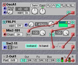
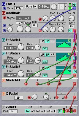
Have a look at the illustration above. A sawtooth waveform from an oscillator is fed into the input of a FltLP lowpass filter. The sawtooth is also fed into the input of a Mix2-1B filter. The output of the filter will be the 'low band' in the crossover filter. This low band is fed into the second input of the mixer. The signal on this second mixer input is brought into antiphase by activating the Inv button. In practice this means that the signal on the second input is not added, but instead subtracted from the first input. On the output of the mixer is the difference signal between the input and the output of the filter, which is 'all but the low band' or whatever the FltLP has thrown away. The advantage of splitting the audio range with this technique is that there are no nasty phase shifts that would occur if both a lowpass filter and a highpass filter were used in parallel, which perhaps many would think to be the obvious way to do it. In this simple crossover filter the high band has a slope that is not as steep as the lowpass filter, e.g. when the lowpass filter is set to 24dB the highband does not have a slope of 24dB. In practice this is not a problem as highpass filters do in general not have to be as steep as lowpass filters to have the right sort of sonic effect. Experimentation and good listening to different settings is necessary to get a good idea of what is happening when tweaking the filter cutoff or changing it to another cutoff slope. Notice that lowpass filters and highpass filters psycho-acoustically work out totally different on sounds. An interesting example is a small sixties transistor radio. The little transistor radio can physically not reproduce frequencies below some 200 Hz, it is just too small for that. In fact, its speaker is an effective highpass filter set to some 200 Hz. Still, when listening to such a radio there is a definite sense of bass notes. Psychoacoustic research has found that if there is only a hinge of harmonics present that belong to a low pitch that is too low to be reproduced by a speaker, a person will reconstruct the sense of this low pitch in the mind. Which actaully applies to any highpass filter. This basically means that whatever a highpass filter throws away the mind will try to reconstruct. The mind does not do this with a lowpass filter. Which means that the issue of slope steepness works out totally different on lowpass and on highpass filters.
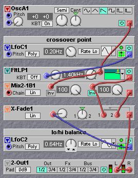
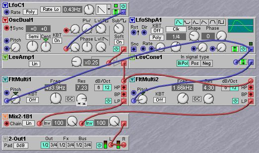
When the two-pole A/B switch is swapped for a crossfade mixer it is possible to smoothly fade between the low band and the high band. If the crossfader is in its middle position the original signal is heard, as this is an equal mix of the low and the high bands. When the crossfade position is moved it will cause one of the bands to be attenuated while the other gets more emphasized. This is very similar to a shelving equalizer where the zero dB point is exactly at the cutoff frequency of the lowpass filter. But this simple patch has several advantages over a standard shelving EQ. First is that the cutoff frequency can be controlled and modulated between extremely low and high frequencies, second is that the balance between the bands can be controlled and modulated between full lowpass and highpass slopes. When used on an audio loop it is possible to fade a loop away in either the low or away in the high, depending on the setting of two knobs, the knob on the crossfader defines if the fade is going into the low or the high and the cutoff frequency of the filter does the actual fade. Third and most desirable advantage is that before the bands go into the crossfader both bands are separately available and can have different additional effects inserted at this point. These effects would have their effect in this band only.
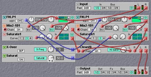
Crossover filters are always good to use before a distortion module. The idea is that distortion often generates a lot of high harmonics which might conflict with the high harmonics already present in the signal. Distortion is often preferred to happen only in either the lower or in the middle ranges of the audio range. By preventing higher frequencies to go into the distortion module much less high harmonics are generated, but the original high is lost as well. By using a crossover filter and mixing the distorted low with the undistorted high, there is suddenly an extra timbre control on any type of distortion. Note that the main distortion will appear to happen in the ranges just above the cutoff frequency of the lowpass filter in the crossover.
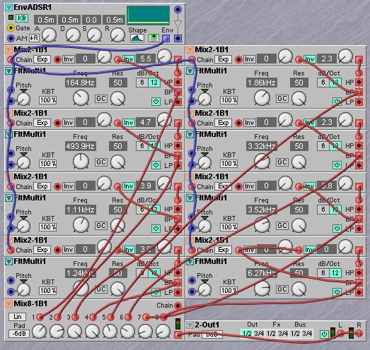
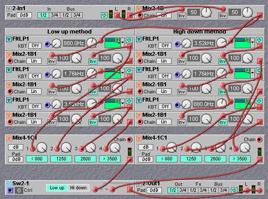
If more than two bands need to be processed, only one extra filter for each band is needed. So if four bands are needed only three filters are actually necessary. Such an array of bandpass filters can be build from either the lowest band up or the highest band down, which in practice does make a difference on how each band sounds. The idea of this cascade of crossover filters is to split a signal in two bands named L and H, then one of the two bands is split and one of them is split, until there are enough bands. The illustration shows the idea better than words can describe it.
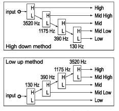
When using this method, the filtering accumulates through the array of crossover filters. If the bandfilters are build up from the low band upwards the lowpass slopes of a band will appear less steep and the highpass slopes appear steeper, while when building from the highest band downwards the bands appear to have steeper lowpass response and less steep highpass response. When listening to only one band in the middle, the low to high method appears to give a bit a higher tuned band than with the high to low method. The choice which method to use is basically a matter of personal taste and might also depend on the sort of audio that is filtered. It is handy to make two similar patches, one with the low up and the other with the high down method and check out which one best serves a particular situation. You will notice that the effect of the bands can be quite subtle, making this type of multiband crossover filter well suited for subtle tonal control on instruments in a mix. This is probably not the type of bandfiltering one would use to create a mastering multiband equalizer, as the bands appear quite shallow. But for the purpose of applying selective distortions and mixing all the bands together again in the end, this bandfiltering works out pretty well. The big advantage is that the crossover frequencies can be freely set to define the width of the bands and virtually any number of bands can be created.
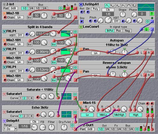
An example of an interesting stereo effect on a mono signal is to split the audio range into e.g. eight bands and then use separate panners with their own lfo on each band. This will transform a static mono signal into a lively moving stereo signal.
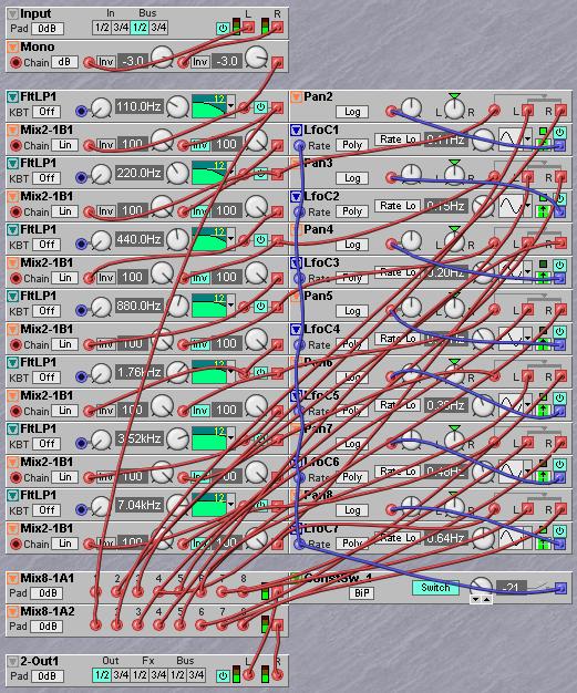
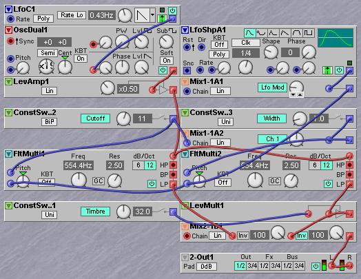
The next patch illustration can be used on e.g. a sampled drumloop. There is saturation on the kick, an area around 3kHz has a MIDI synced echo. The area between 110 Hz and 3kHz plus the highest band above 3.5kHz are autopanned in reverse with a MIDIsynced Lfo.