 Micro Ace ED73 with
unmodified bogie sideframes
Micro Ace ED73 with
unmodified bogie sideframesChanging the bogie sides on Micro Ace's ED73
> main > modeller's corner > Micro Ace ED73
kill level: Intermediate to high
Tools needed: Tweezers, lots of patience, small Phillips-type screwdriver, small screwdriver
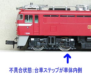
Unfortunately Micro Ace supplied their model of the ED73 electric loco with the bogie sides mounted the wrong way. The steps that lead to the driver's cabs are in the wrong place, under the side of the machine room instead of under the cab doors. You can not simply dismantle the bogies and flip around the sideframes and then reassemble the bogies. For a correct model of the ED73 you need new bogie sideframes, which are available through your dealer. If this modification is beyond your skills, it is best to have it done for you by Micro Ace, just send the model back to Micro Ace through your dealer, Micro Ace's rates are reasonable.
Micro Ace ED73 with
unmodified bogie sideframes
Step 1 Disassemble bogies
To start modification disassemble the bogies, the sideframes clip to the bogie frames, the notches are located at the ends of the bogies. You need a small screwdriver to pry out the bogie frames a little. Be careful not to break or loose any parts. By accident, I took off the bogies, which resulted in a complete disassembly of the loco, which took a lot more work to re-assemble than anticipated. I recommend that you leave the bogies under the loco.
Step 2 Change sideframes
This is the easy part. Simply replace the sideframes and driving wheels (one assembly) and then re-assemble the bogies. Everything just clips together, be sure that the wheels are moving freely and do not jam. If you took off the bogies from the loco, it's very easy to replace the sideframes, but re-assembling the loco is a lot of work (which took me several hours!)
Step 3 Re-assembling the loco
This is only needed when you took off the bogies from the loco. Reassembling is a lot of work and you need to work patiently and carefully. First put the bogies back under the loco. The bogies are mounted on a kind of bolsters, the gear towers are on the outer ends of the bogies to clear the bolsters. There's a small pin on the loco part of the bolsters which mate with a small hole on the bogie part of the bolsters. Then place the motor, please observe the position of the motor, it fits only one way, there are small recesses in the loco frame which give some room for the brush caps. This also ensures the correct function of the light switch (mounted on the underside of the loco frame). Finally mount the printed circuit board. Then test run your locomotive. If everything works OK, then put back the loco body shell, which just clips on. Then again do some test running. If everything is OK you're finished and you can enjoy a fine-running and nice looking loocmotive.
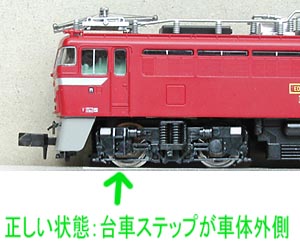 The
result of the modification
The
result of the modification
Some notes:
The body of this model is easier to remove than on some older Micro Ace locomotives. If needed you can slide 10 thou styrene strips under the notches which hold the loco body. These are located just under the cab's side windows. Normally you can just pry out the body sides.
The headlights on this model are fairly dim, which is also the case with other Micro Ace loco models. Using a Tomix 'CL' controller or other high-frequency lighting system brings only a little improvement. There's a little space above the printed circuit board which may be enough to fit a DCC decoder. Please choose a thin one like Lenz LE0511 or LE0521, Tran DCX74 or Zimo MX62. For Selectrix the DHL100 or DHL050 may be a good choice, Tran DCX74 preferred, it's only 1.8 millimetres thin.
Disclaimer
This text reports the author's personal experience. If you are doing this modification, you are the only one responsible of success or failure of this project. The author can not be held responsible of success, failure, injury or damage.
< Back to the modeller's corner
![]() Modelling
Modelling ![]() Layouts
Layouts ![]() Modeller's
Corner
Modeller's
Corner ![]() Train
Simulators
Train
Simulators ![]() Various
Various