KISS 70W POWER AMPLIFIER USING VHF BIPOLAR TRANSISTORS
(Published in RSGB's RadCom aug 1991)
Experimental phase
EXPERIMENT
This 10 - 80 m amplifier is using two VHF bipolar power transistors PHILIPS BLW60. The gain of a VHF bipolar transistor can be very high but the amplifier (schematic) was perfectly stable in the experimental phase. I expect the BLW transistors could be replaced by similar VHF-types due to the heavily collector to base feedback.
|
|
It is possible to build this KISS amplifier successfully with the brief information shown on the schematics. The amplifier performs well with a two-tone test and on-air reports are excellent when using a Yaesu FT-7 as the (10 W) driver.

|
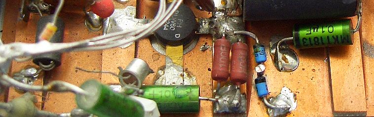
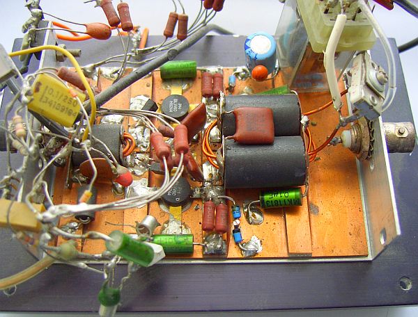
5 – 8 mm-wide cut-out strips of PCB are glued on the board and used as copper pads. |
No PCB need be made. Copper clad epoxy is used upside down. The copper side forms the "ground" and 5 mm wide cut-out pieces of copper clad epoxy are glued to the copper as stand-off/soldering pads etc. The epoxy side is bolted to a heat sink.
OUTPUT LOW-PASS (LP) FLTER
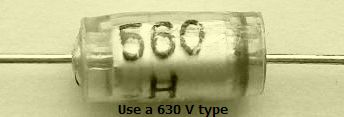
At present I use 630 V polyester caps (fig») for mij LP filters.
OUTPUT BAND-PASS FLTER
|
These components are suited for 100 W transmitters. |
In "Band-pass filters for HF transceivers", QST 1988-09, K4VX provides details of these three-pole Butterworth band-pass filters for cleaning-up the harmonic output of any low- or medium-power transmitter. It also provides filtering in the receiver mode, helping to reduce front-end overload problems and limit the number of strong broadcast signals entering the receiver.
![]()
![]()