|
|
|
MAGNETIC LOOP "MEIGHT"
A FIGURE-8 DOUBLE LOOP ANTENNA (magnetic eight)
(MEIGHT Magnetic Eight in RSGB's RadCom May 1997)
|
|
|
INTRODUCTION
Much has been published about magnetic antennas. Their performance on the air with a loop circumference shorter than ¼ λ often belies their low theoretical efficiency. There remains the narrow bandwidth, which often requires elaborate tuning provisions.
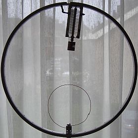
I thought that two loops shaped as the figure-8 might bring relief and that with two paralleled loops the impedance at the tuning point might decrease and that the magnetic fields support each other. So I tried it on 145 MHz, a size very convenient for experimenting.
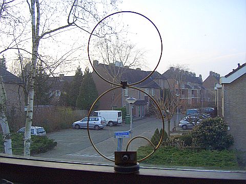
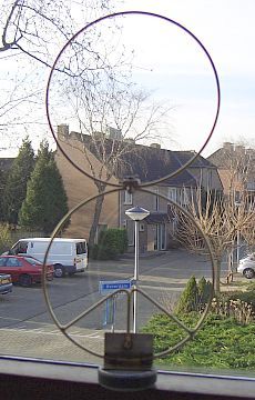
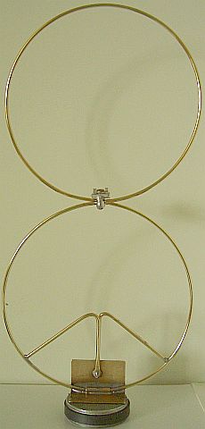
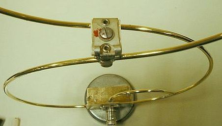
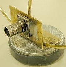
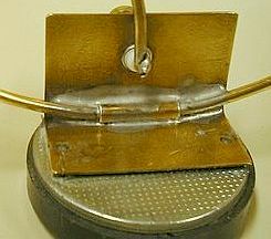
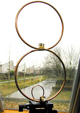
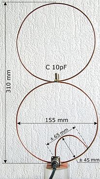
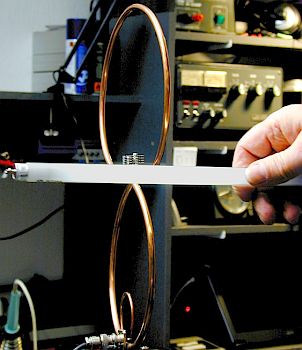
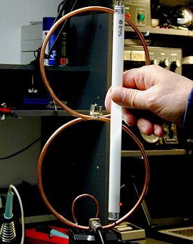
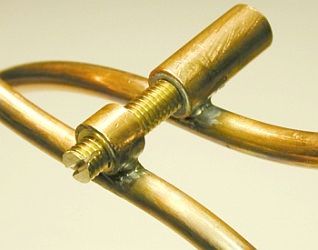
The figure-8 double loop shown (fig») is resonated with a piston trimmer which also mechanically separates the two conductors at the crossover.
|
FEEDING
Combimatch. |
Quasi delta match. |
|
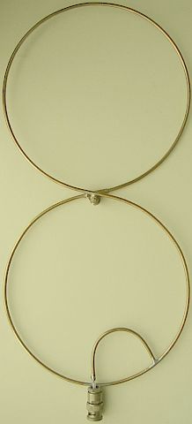
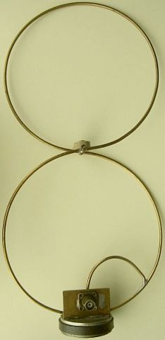
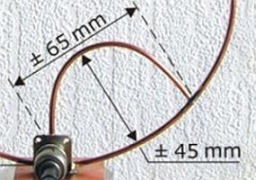
Neither the usual coupling loop or gamma match satisfied me, then the idea occurred of combining the two: it worked, and I call it Combimatch («fig). However this loads the antenna unsymmetrical so I was looking for a more symmetric system. It turns out that a delta match was the answer whereby one part is not connected to the feeder line but loads the loop similar as the other half with the connected coax cable. This feeding system, I call it "quasi delta match", perform as the combimatch but loads the loops more symmetrical.
CONSTRUCTION
|
|
|
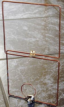
The double-loop (15.5 cm diameter) was shaped from a 1 m length of 3 mm diameter brass welding rod. Using thicker copper tubing may increase the efficiency. A can with an approximate diameter of 12 cm makes a good bending jig. The loop was closed at the crossover by soldering the rod ends into a 2 cm long tube with an inner diameter of 3 mm.
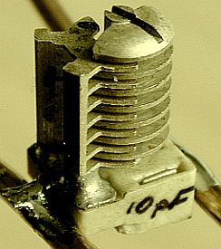
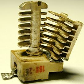
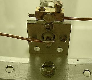
The tuning capacitor is a 10 pF ceramic piston trimmer or mica stamp trimmer which were adequate at a power of 10 W. For outdoor use, some kind of weatherproof enclosure for the trimmer will be required.
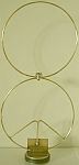
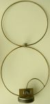
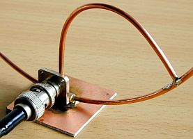
One antenna is mounted on a short length of angle profile, which also carries a BNC socket. The assembly is then cemented at the feed point onto a magnetic mount for mobile use. In another version the loop is soldered onto a BNC plug for direct installation on a handheld transceiver.
The Combi-match is also made of brass rod, but only after trial with one made of soft copper wire. It turns out that the precise attachment for a point with best SWR depends on the way the BNC connector is mounted.
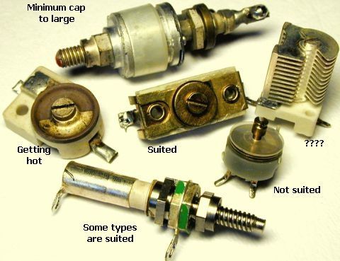
Generally one emphasises that the capacitor must be a high RF voltage type, but little attention is given on the large flow of RF current which can run. That appeared already with a power of 10 W, because some ceramic trimmers became considerably warm and that changes the capacitance. After polishing the brass that phenomenon was much less, a proof of large VHF current on surface of the rod. For use outside the capacitor should be protected with a housing l against protect against influences of weather.
TUNING AND TESTING
Adjust the trimmer with a non-metallic tool and find the precise attachment point of the combi-match for unity SWR at the operating frequency. The 2 : 1 SWR bandwidth is around 1 MHz.
|
Left: The radiation direction at a circumference<¼λ and vertical polarisation Right: The radiation direction at a circumference>¼λ and horizontal polarisation |
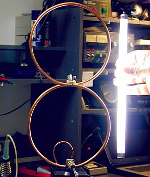
Polarisation is exactly vertical at a circumference < ¼ λ. The azimuth radiation pattern is figure-8, with very narrow nulls. Surprisingly, the nulls are not noticeable in mobile operation. In fact flutter seems to be less bothersome than with the usual ? λ or ? λ mobile whip. Note: if the circumference > ? λ the polarisation becomes horizontal!
Efforts to use a second antenna as a parasitic element to improves the gain or change the pattern were unsuccessful.
I would like to hear from anyone who has tried the figure-8 MEIGHT loop antenna on lower frequencies, e.g. 10-80 m.
CAPACITORS
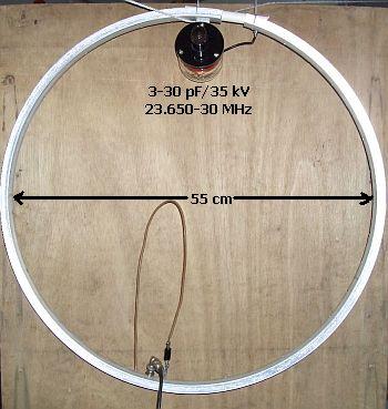
TEST A LOOP FOR HF
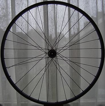
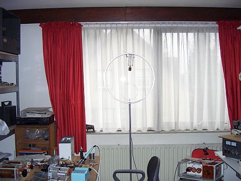
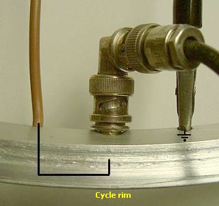
I used an aluminium cycle wheel for the loop. With a 16 - 150 pF cap the range was 11 - 30 MHz.
Matching the coupling.
|
With a 100 pf cap the range was 10 - 14 MHz. |
Hairpin coupling |
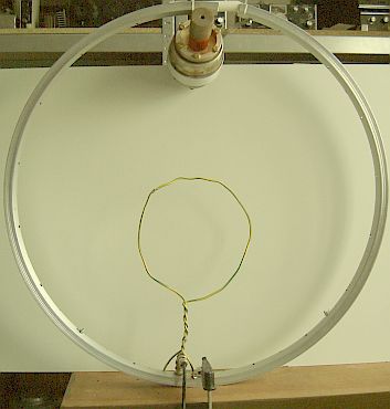
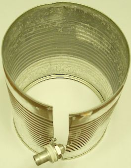
Coupling with 2 turns of 8 cm diameter, 1 turn of 12 cm diameter or with a tin-can.
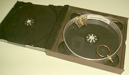
PA1AMS's test with a "CD" sized 145 MHz loop.
PA9OK's (SK) EXPERIMENTS
|
|
|
Radiation pattern
|
Vertical polarization (tx = 10 W). |
Minimum horizontal polarization. |
Zero horizontal polarisation. |
|
The result of the VHF current. |
A home made capacitor with Delrin insulation was getting hot. |
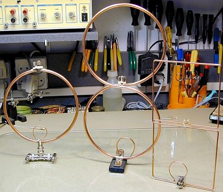
The tested loops.
![]()
![]()