THE OCF FD4 (FD3) WINDOM ANTENNA
![]() 19 may 2011
19 may 2011
FD4 (80/40/20/10 m)
The 4-band Fritzel model FD4 is a special version of a Windom antenna. It is a half-wave long on the lowest frequency, and is fed from a coax cable through a transformer inserted in the wire at one-third from one end. Fritzel used the shown dimensions of 13.8-m and 27.7-m in the 1960s.
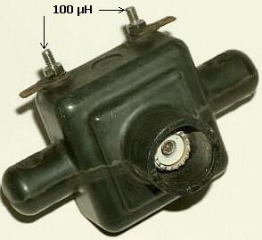
A 1 ÷ 6 auto transformer matched the antenna to the 60-Ω coax then commonly used in Germany. For 50-Ω coax a 1 ÷ 7 ratio would be a better choice. The Fritzel series 70 transformer (fig») has, on the antenna side, an impedance of 100-µH, approx. 2200-Ω at 3.5-MHz, i.e. more than 5 times the antenna impedance at that frequency; an excellent value.
It so happened that I was then experimenting with the same system of antenna and trying to determine the best dimensions. Copying the dimensions shown above gave good results and saved me much pruning and reinstalling. On 3.5-MHz, however, the SWR was high.
Not surprising, as the antenna length was more than a half wave. I found that a 100-pF capacitor between the longer wire and the transformer brought the 3.5-MHz SWR down and barely affected the other bands. The capacitor is a transmitter type or about 1-m RG58 coax cable. Remove 1-cm of the braid on both ends and butter it with transparent contact adhesive and reassembled with heath shrink tubing. The process with the transparent adhesive is for preventing that water gets inside the cable.
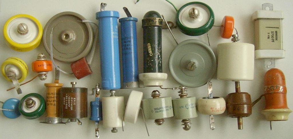
Examples of capacitors used in amplifiers and transmitters.
FD3 (40/20/15 m)
The Fritzel FD3 is a half-size version of the FD4, which resonates on 40, 20 and 10-m. 15-m, can be added as described below.
SWR
The SWR data for 80, 40, 20 and 10-m, supplied by the manufacturer, are correct only if the antenna is installed in a straight line. The proximity of conducting surfaces or structures can be detrimental to the SWR. Low height above earth, nearness to large conducting surfaces or installation as an inverted-V may shift the resonance frequency on one or more bands.
IMPEDANCE
Most Dutch amateurs cannot hang their antennas very high and that affects the feed point impedance. For an FD4 under those circumstances, 340 – 360-Ω for the resistive part of that impedance is a reasonable assumption. Some amateurs then assume that, with the appropriate transformer ratio, the transmitter sees the proper 50-Ω load but this is seldom true. The coax works as an impedance transformer, sometimes producing unfavourable impedance at the transmitter end. That is why specific lengths of cable are frequently recommended. I always use 27.2-m of 50-Ω coax with a velocity factor of 0.66: RG213 or RG58.
5-BAND FD4 (80/40/20/15/10-m)
Hang a 21-MHz Windom («fig) parallel to the FD4, as show, to cover 15-m as well.
If you (fig ») used insulated wire for the antenna the reduction factor is about 90%. The calculated electrical length of an antenna leg is L= (L1+ L2+ L3) × 0.9! The beginning of the wire (L1) goes through the suspension hole, then back to the main wire (L3) and then to the connecting terminal of the balun.
If possible hang the 15-m band antenna at right angles to the FD4.
I had no room for the extra wire and it was hung under the main antenna. It worked satisfactory both at home and in Lebanon.
FD3 (+ 80m) & FD4 (+160m)
|
|
|
Because the limited spaces in my back garden I was forced to decrease the length of a FD4. So I did experiments with a FD3 for an added 80-m range, see the schematic.
I can not exactly remember the length between the 78-µH coil and the far end of the dipole, but start with a 4 m long wire and check the resonance and then cut the wire for your favourite frequency. However, much depends on local conditions such as height and metal objects in the vicinity. The bandwidth at 80-m is narrow comparable with a whip on an automobile. If you are matching with a tuner, the antenna can be used over a wider range.
At my request SMØFLY calculated the 3-m & 78-µH extension with an antenna program. The resonance of the antenna at about 15-m height was close to 3.7 MHz.
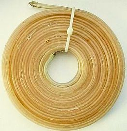
More bandwidth can be obtained with the rolled up ribbon stub system («fig).
DL1JM did likewise experiments with a FD4 converted to a 160-m range, see:
http://www.mods-ham.com/02_Mods/Other-Mods/FD4-Umbau/FD4_Umbau-Erweiterung.htm
SHORTED FD4 (a modified K3AZ antenna)
|
|
The modified W1SE ex K3AZ antenna becomes a FD3 sized FD4 with a 6 ÷ 1 or 4 ÷ 1 balun. The SWR on all bands will not be as good as an original FD 4, but with a built-in or external tuner you can use this antenna. I had that system for about 4 years. Suitable ATU's are for example my Fri-Match, a two-button system for 10 to 80-m or any other asymmetric tuner such as T-match, LC loop, Pi-filter, etc. One advantage is that the rolled-up stub and balun (fig») can be constructed in one enclosure as an insulator.
|
Ribbon line. |
Stub made with Rolled up ribbon line. |
OCF/WINDOM
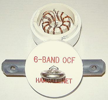
Fritzel with his FD4 design has others encouraged to produce or experiment with off centre feed (OCF) antennas. Currently, there are a lot of such types under many names listed. These OFC's have been other dimensions and are often suitable for some WARC bands. The feed point is at 33% of antenna length.
|
height 5 - 10-m » 4 ÷ 1 balun height 10 - 15-m » 5 ÷ 1 balun height >15 - 20-m » 6 ÷ 1 balun |
The height above ground will affect the feed point impedance and the transformation ratio of the balun. The lower the antenna the lower the impedance of the feed point. A rule of thumb is (fig»):
If you want to experiment then takes account of these data.
2EØZEH has built a 40-m OCF dipole and would like to add an extension for 80-m. Here are a few possibilities for an 80-m antenna in the limited space. It is necessary to experiment for the length of the ladder line.
|
2E0ZEH's version of an OCF. |
|
Some of my not tested ideas to extend this 40-m OCF with 80-m.
MORE BANDS
It is shown that FD3 and FD4 have resonances in the WARC bands, but I have no practical experience because I had no equipment for 160 m and the WARC bands at the time of my experiments. At point A (the"Windom"point) of the graph (fig») you can see that the antenna on 40 and 80-m have equal impedance. It is not drawn but the same point also applies to the 10 and 20-m band. That means that at the one feed point the antenna is suitable for 10, 20, 40 and 80-m.
Such reasoning applies to points B and C for 30 and 80-m and point D for 80-m and 30-m. Apparently by choosing on a clever way the length of both wires the antenna ca be used for more than 4 bands.
|
80-m SWR = 1.7 |
20-m SWR = 1.5 |
12-m SWR = 1.5 |
|
40-m SWR = 1.3 |
17-m SWR = 1.3 |
10-m SWR = 1.3 |
LA1TNA claims for FD4 an SWR of (fig »):
The antenna is also suitable for 160 m if you replace the 13.5-m leg of a FD4 by a length of 54-m. The total length is therefore 27.7 + 54 = 81.7-m!
LF DETECTION THROUGH THE TRANSFORMER
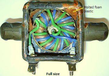
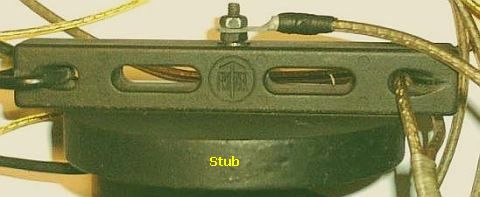
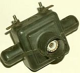
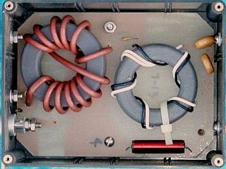
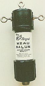
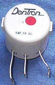
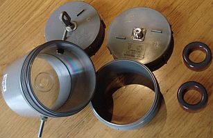
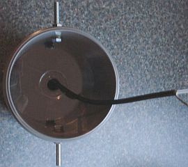
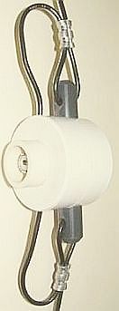
 At the time I was given a (low power) Fritzel series 70 6 ÷ 1 ‘balun’, damaged by its owner who had applied 400-W on 21-MHz to it. The case had been cracked open («fig) and had partly molten, but the contents were OK. I found that the so-called ‘balun’ was not a balun at all but an auto transformer, with a direct connection between the outer of the feeder and one of the two antenna wires.
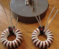
That explained why many amateurs with an old model Fritzel ‘balun’ were bothered by LF (coming from the radiation of the coax cable) detection in their own or their neighbour’s equipment. I advised them to install a choke balun near the auto transformer consisting of eight turns of the coax wound through a green Philips 3E1 toroid, which fixed the problem; see also 'feeder radiation', below.
For my own experiments I used a true 4 ÷ 1 balun in the antenna and, below it, a 1.5 ÷ 1 or 1.7 ÷ 1 auto transformer for a match to a 50-Ω coax and did not experience that problem.
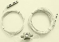
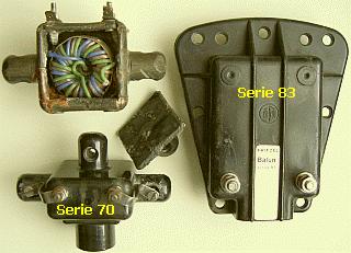
An autotransformer and choke balun were fitted in the case (insulator fig») of the series 83 balun so that the unwanted current on the braid is suppressed and reduces interference in other apparatus. It's not wise to load an original FD4 with high power on the 15-m band.
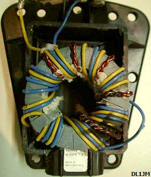
DL1JM sent a photo of an overloaded Fritzel series 83 1 ÷ 6 balun. It was damaged by flashover, a result of too much power and the intrusion of dust and dirt on the twisted copper wires. You can clearly see the two black spots in the picture. He repaired and improved the balun with Teflon insulated wire, removed the 1 ÷ 1 (choke)balun and replaced it by a W2DU type. The latter consists of 25 ferrite toroids on the coaxial cable close to the feedpoint. (See an example below) The renewed balun now works perfectly with high power in combination with a FD4 + 160-m extension, see up in this article.
FEEDER RADIATION
|
Choke baluns. |
Balun: left serie 70, right serie 83. |
|
Choke balun. |
|
Experimentation with the original Fritzel transformer has shown that the antenna can function as an inverted-L if the feeder does not run at right angles to the antenna. The part of the antenna nearest to the feeder radiates most and operates like an inverted-L with the outer of the coax.
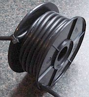
A choke balun between the transformer and the feeder prevents this. 3 – 4-m of RG58 coax wound on a former of 7 – 10-cm diameters will do and can handle 400-W.
Obviously, Fritzel have discovered that too. Since 1980, the housing and power capacity of their series 83 contains not only the 6 ÷ 1 (fig») transformer but also a choke balun; the strain insulators have also been changed.
Still it is better to route the coaxial cable line to the shack by running it at least 5 m to the ground and then at a 90° degree away from the antenna.
With an eventually extra choke balun the 3 – 4-m coax used for the balun becomes a part of the recommended 27.2-m length (fig»).
Some Windom-derived antennas enhance feeder radiation on purpose. One example is the Carolina Windom (USA) which provides both, horizontally and vertically polarised radiation.
An FD4 is often be titled as being a dummy-load, but that is mostly hearsay or because one of the side effects have occurred. If proper matching and suppression of feeder radiation are taken care of, this antenna works as effectively as any other radiator of the same length and location.
MATCHING (1)
Matching a 50-Ω cable to an FD4 requires a balun and an impedance transformation of 1 × 7 (1 × 6.7) On the feeder side there is a choice between a choke balun and a trifilar 1 × 1 balun. Two violet Philips 4C65 toroids, T2 and T3, are required to make the 1 × 7 balanced impedance transformer.
MATCHING (2)
It can also be done with only two cores but then it is difficult to get all the windings of suitably insulated wire onto T2, which then also can handle less power.
It should be possible to do it with thin insulated wire as shown in the right-hand photograph. It shows, here only as an example, the balun system of a Cushcraft R5 antenna. The bifilar 10-turn coils are placed over the centre of the 16-turn winding. Use wire with good insulation. In the photograph, the brown coax on the left core and the wire on the right core are Teflon insulated.
MATCHING (3)

An insulation transformer T1 with an impedance ratio of 1 ÷ 1.8 (1 ÷ 1.78) raises the impedance level from unbalanced 50 Ω to a reasonably balanced 90-Ω. Thereafter, T2 (T3), a 1 Χ 4 ‘balun’ connected as a balanced transformer, raises that to 360-Ω. I prefer this feed system because there is no galvanic connection between coax and antenna, minimising the danger of RF on the coax outside.
Of the 1 ÷ 4 schemes, I prefer the right-hand one because it provides the better symmetry. In lieu of the bifilar windings on T2 and T3, coax can be used.
|
|
Winding scheme for a 1 ÷ 1 balun.
|
A simpler but still effective way of feeding an FD4 is a single 1 ÷ 4 balun and an ATU. Most often the SWR then is less than 2 ÷ 1, which an ATU in or near the transceiver can handle without appreciable losses. That avoids the somewhat difficult task of making a 1 ÷ 6 or 1 ÷ 7 transformer. On the lower bands, a 1 ÷ 4 balun provides a lower SWR than a 1 ÷ 6 or 1 ÷ 7 transformation.
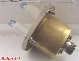
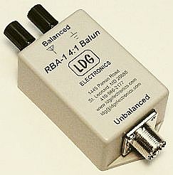
4 ÷ 1 Baluns.
EXTRA BANDS
It seems that the FD3 and FD4 also have resonances in the WARC bands.
|
80-m SWR = 1.7 |
20-m SWR = 1.5 |
12-m SWR = 1.5 |
|
40-m SWR = 1.3 |
17-m SWR = 1.3 |
10-m SWR = 1.3 |
I cannot confirm this as my tests were conducted before these bands were available but LA1TNA claims the following for the FD4:
If the 13.5-m wire of the FD4 is extended to 54-m, the antenna also works on 160-m but who has room for a span of 27.7 + 54 = 81.7-m?
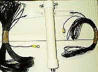
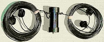
A FD4 and a 1 ÷ 4 balun works well PA3EYK wrote, he made an OCF antenna and used it mainly for 80 and 160-m. He experimented first with 55.5-m and 28.5-m of 2-mm diameter aluminium wire about 10-m above the ground. It is pretty bare wire, have good conductivity and a pulling force of 130-kg.
He was looking for a resonance on 80 and 160-m by gradually cutting both ends of the antenna. Finally he achieved resonance at 1850 and 3650-MHz and lengths of 27.5 and 53 meters. On the higher bands the SWR was not as good, but for him unimportant because he used an ATU to lower the SWR.
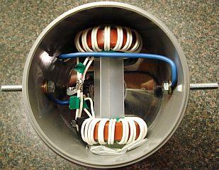
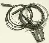
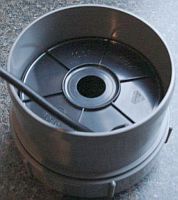
The balun was made with two T200-2 toroids and a choke balun of 6-m coax on a coil former. Everything was mounted in standard PVC housing with in the lower part the rolled coax cable. The photos will be clear enough for home brewers. I think that the inductance of about 7 μH (2 × 17 turns in series) to the secondary side of the balun is rather low for 80 and 160-m, but apparently it works to his full satisfaction.
BUYING
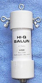
If the shopping for components and assembling an FD4-like antenna does not appeal to you, you will have to buy one. Several big and small antenna manufacturers offer similar products under fancy names such as OCF Windom. They continue to be secretive of the innards of their balun & matching units, and it largely determines the performance of such antennas. You only can go by the opinion of other buyers, be they expert or not.
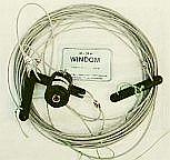
FD4 clones.
FD4 CLONES
|
3.5 SWR = 1.1 |
10.125 SWR = 1.7 |
24.9 SWR = 1.3 |
53 SWR = 1.0! |
|
3.8 SWR = 1.1 |
14.250 SWR = 1.6 |
28.25 SWR = 1.1 |
– |
|
7.1 SWR = 1.5 |
21.250 SWR = 1.8 |
29.25 SWR = 1.3 |
– |
The manufacturer of the antenna on the right is VK3KCG. He calls his 2-part balun an ‘Open Path Magnetic Balun’. The resonant frequencies with the lowest SWRs at an antenna height of 6 m are:
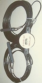
This is yet another clone. The balun obviously is an autotransformer and the manufacturer is not secretive about it. As described above, this increases the risk of feeder radiation.
![]()
![]()