|
TLT-Mode mixer
Gennady Bragin, RZ4HK, has developed a promising switching mixer that has some things in common to the "classic" H-Mode mixer. The schematic supplied by Gennady is shown below.
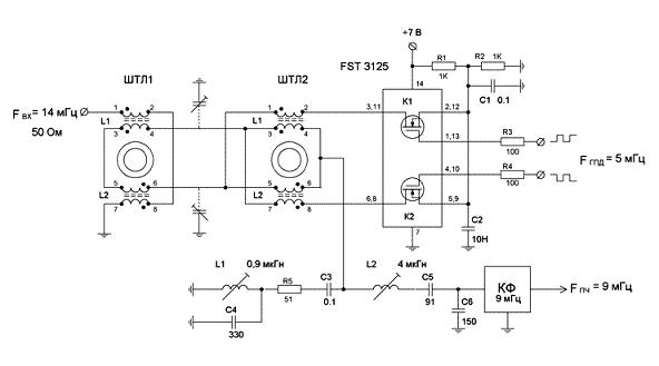
Like with the H-Mode mixer the sources of the MOSFET switches are connected to ground and are therefore not modulated with the mixer's signals, minimizing IMD. The commutating action is actually done by the transformers, but in case of the TLT-Mode mixer by means of transmission line principles.
With the H-Mode configuration, transformers have proven to be very important in the mixers real-life IMD behavior as a function of frequency. Therefore the TLT variety is very promising as TLT transformers can be made very lossless and wideband.
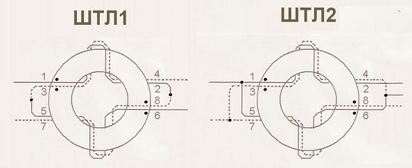
The construction details of the transformers used by Gennady are shown in the following picture. He is combining the 4 transmission lines on 2 cores. The transmission lines have only 2 turns and the core is specified as a ferrite ring of size 10x6x5mm and a mu of 1000.
Using the above information I have built a version of the TLT-Mode mixer in order to test its performance from 160M up to 4M. The following changes however were made to the original design:
- Transformers
The best matching toroid regarding size and material available to me is the FT37-43 with a mu of 850. It is only slightly smaller than the one used by Gennady. After analyzing the frequency response of the transformers with only 2 turns per transmission line it turned out that this is not enough to cover the HF bands including 160M. With 5 turns the transformers performed well down to 1MHz. Self resonance was above 100MHz.
- Switches
Using FSA3157 rather than FST3125 eliminates the need for complementary LO signals. The single SPDT FSA3157 seems ideal for this application. The original shows FST3125 switches used in parallel. I found the Ron of FSA3157 to be low enough to be rather insignificant with respect to the transformer losses, so a single FSA3157 SPDT switch is used.
- Balancing
The original schematic shows two balancing trim capacitors used to tune the mixer for perfect symmetry. The TLT-Mode mixer is tested as a wideband HF-VHF mixer from 160M up to 4M, so the trim capacitors cannot not be used. It would require a separate adjustment for each band, which is not practical. Rather than relying on trim capacitors for balancing, the mark/space ratio of the LO is used, which can easily be made band specific with DAC control. The 2 transformers are constructed as symmetrical as possible.
- Termination
The original schematic shows a diplexer and crystal filter, which are strictly not part of the mixer circuit. I am using the same IF termination used with all the other mixer configurations tested so far. (Diplexer + 9MHz Quad hybrid roofing filter with an extra attenuator between the mixer and the roofer in case of IMD measurements.)
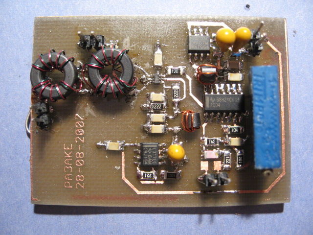
The resulting experimental TLT-Mode mixer assembly is shown in the following picture:
The next table shows the results of the measurements:
| FSA3157 + 2xFT37-43 5 turns + 74AC04 |
Vdd = 7.0V, Vbias = 2.5V |
Best bias |
| Band |
BPF |
mixer |
MDS -dBm |
IF rej |
spur |
mixer IIP3 (dBm) @ 20KHz spacing |
Bias |
IIP3 |
| IL |
CL |
- |
+ |
|
avg |
-6 |
-3 |
0 |
+3 |
+5 |
|
0 |
| -dB |
-dB |
BPF |
BPF |
-dB |
dB |
dBm |
dBm |
dBm |
dBm |
dBm |
V |
dBm |
| 160 |
3,3 |
4,76 |
134,0 |
130,0 |
36,0 |
|
|
|
34,9 |
|
|
2,5 |
34,9 |
| 80 |
1,4 |
4,72 |
134,0 |
132,0 |
36,0 |
|
39,5 |
40,2 |
41,0 |
41,5 |
41,5 |
2,5 |
41,0 |
| 40 |
2,3 |
4,68 |
134,0 |
131,0 |
35,6 |
|
|
|
52,2 |
|
|
2,5 |
52,2 |
| 30 |
3,4 |
4,68 |
134,0 |
130,0 |
36,0 |
|
|
|
48,0 |
|
|
2,5 |
48,0 |
| 20 |
3,4 |
4,52 |
134,0 |
130,0 |
38,0 |
|
|
|
47,2 |
|
|
2,5 |
47,2 |
| 17 |
3,0 |
4,64 |
134,0 |
130,0 |
36,0 |
|
|
|
45,3 |
|
|
2,5 |
45,3 |
| 15 |
3,9 |
4,76 |
134,0 |
129,0 |
34,0 |
2,9 |
|
|
42,6 |
|
|
2,5 |
42,4 |
| 12 |
3,7 |
4,68 |
134,0 |
129,0 |
33,6 |
|
|
|
39,8 |
|
|
2,5 |
39,8 |
| 10 |
2,3 |
4,52 |
134,0 |
131,5 |
32,4 |
|
|
|
38,0 |
|
|
2,5 |
38,0 |
| 6 |
|
4,32 |
132,0 |
|
26,0 |
|
|
|
39,2 |
|
|
3,0 |
40,7 |
| 4 |
|
5,60 |
132,0 |
|
18,0 |
|
|
|
36,9 |
|
|
2,7 |
36,9 |
Conversion loss is excellent from 160M to 6M hovering around -4,6dB. This is the best CL I have seen so far!
IP3 is peaking to a staggering +52dBm on 40M. Below 40M premium IP3 is not maintained, probably due to the transformers. Also on the high bands IP3 gets worse. With transformers using 2 turns it is possible that the IP3 peak of +52dBm occurs on 30M or 20M. I have not tried this however, as I am interested in a wideband HF mixer.
9MHz IF rejection is poor, only -36dB and even less on the high bands. It seems difficult with this configuration to get good balance, at least without the frequency dependent trim capacitors.
Sensitivity to the bias point is minimal. Only on 6M and 4M there was some sensitivity to the bias point. This is much like the behavior of most H-Mode mixer configurations with 1:1 transformers.
IP3 linearity on 80M is good. IP3 remains constant over a wide range of 2-tone input levels.
With regard to the suppression of DDS spurs, the results are average: +2.9dB average spur level on 15M. Given the poor IF rejection this is actually quite good.
The weakest point of my build of the 2 transformer TLT-Mode mixer is the poor IF-rejection. It should be possible to improve symmetry in a frequency independent manner. The most obvious thing to do is to connect the 3+5 connection of L1 and L2 of the input balun to RF-ground with a 100nF capacitor. This will force balance to the circuit that is otherwise floating around with parasitic capacitance. RF-IF isolation improved considerably to about -50dB, but strange things happened to the conversion loss. The CL took a hit of about -7dB extra resulting in -12dB conversion loss! The combination of 2 transmission lines on each core seems to have some side effects and the next step was to use 4 separate transformers.
The following measurements are the result of a 4 transformer TLT-Mode mixer with Mini-Circuits T1-1 transformers, supplied by Colin, G3SBI. The 3+5 connection of L1 and L2 is grounded with 100nF:
| FSA3157 + 4xT1-1 + 74AC04 |
Vdd = 7.0V, Vbias = 2.5V |
Best bias |
| Band |
BPF |
mixer |
MDS -dBm |
IF rej |
spur |
mixer IIP3 (dBm) @ 20KHz spacing |
Bias |
IIP3 |
| IL |
CL |
- |
+ |
|
avg |
-6 |
-3 |
0 |
+3 |
+5 |
|
0 |
| -dB |
-dB |
BPF |
BPF |
-dB |
dB |
dBm |
dBm |
dBm |
dBm |
dBm |
V |
dBm |
| 160 |
3,3 |
5,84 |
133,5 |
129,5 |
68,4 |
|
|
|
39,2 |
|
|
2,5 |
39,2 |
| 80 |
1,4 |
5,60 |
133,5 |
132,0 |
72,8 |
|
42,2 |
44,2 |
45,0 |
46,0 |
43,7 |
2,5 |
45,5 |
| 40 |
2,3 |
5,56 |
133,5 |
131,0 |
74,4 |
|
|
|
48,4 |
|
|
2,5 |
48,4 |
| 30 |
3,4 |
5,52 |
134,0 |
130,5 |
70,8 |
|
|
|
46,5 |
|
|
2,5 |
46,5 |
| 20 |
3,4 |
5,56 |
134,0 |
130,5 |
70,4 |
|
|
|
44,4 |
|
|
2,5 |
44,4 |
| 17 |
3,0 |
5,64 |
133,5 |
130,0 |
70,4 |
|
|
|
42,1 |
|
|
2,5 |
42,1 |
| 15 |
3,9 |
5,68 |
133,5 |
129,0 |
74,8 |
-1,3 |
|
|
40,9 |
|
|
2,5 |
40,9 |
| 12 |
3,7 |
5,76 |
133,5 |
129,0 |
70,0 |
|
|
|
39,8 |
|
|
2,5 |
39,8 |
| 10 |
2,3 |
5,88 |
133,5 |
131,0 |
72,4 |
|
|
|
39,5 |
|
|
2,5 |
39,5 |
| 6 |
|
6,24 |
133,0 |
|
66,4 |
|
|
|
38,7 |
|
|
2,5 |
38,7 |
| 4 |
|
6,68 |
132,0 |
|
71,2 |
|
|
|
33,9 |
|
|
2,5 |
33,9 |
IF-rejection is solved. On almost all bands it is possible to reach -70dB, which is excellent. The values listed are the best values obtained on each band. When adjusted for best results on 15M the other bands are still between -40dB and -50dB.
Sensitivity to the bias point is minimal. One adjustment for all bands is sufficient.
The IP3 is again at its best on 40M, but not reaching +50 anymore. The T1-1's improve the IP3 on 160 and 80M considerably.
The average DDS spur level on 15M is fairly good at -1,3dB. Given the excellent IF-rejection better results were expected though.
The weakest point of this configuration is the conversion loss around -5.6dB on most bands. The datasheet of the T1-1 transformer does not show the best possible figures for IL either, so the T1-1's are probably not the most suitable transformers. A better candidate is the T1-6, of which the center-tapped version T1-6T did extremely well with the classic H-Mode mixer.
The following table shows the results with the T1-6 transformers:
| FSA3157 + 4xT1-6 + 74AC04 |
Vdd = 7.0V, Vbias = 3.0V |
Best bias |
| Band |
BPF |
mixer |
MDS -dBm |
IF rej |
spur |
mixer IIP3 (dBm) @ 20KHz spacing |
Bias |
IIP3 |
| IL |
CL |
- |
+ |
|
avg |
-6 |
-3 |
0 |
+3 |
+5 |
|
0 |
| -dB |
-dB |
BPF |
BPF |
-dB |
dB |
dBm |
dBm |
dBm |
dBm |
dBm |
V |
dBm |
| 160 |
3,3 |
4,64 |
134,5 |
130,5 |
60,4 |
|
|
|
50,4 |
|
|
3,0 |
50,4 |
| 80 |
1,4 |
4,60 |
134,5 |
132,5 |
60,4 |
|
46,0 |
48,7 |
51,2 |
53,7 |
40,7 |
3,0 |
51,2 |
| 40 |
2,3 |
4,72 |
134,5 |
131,5 |
60,0 |
|
|
|
46,4 |
|
|
2,5 |
46,9 |
| 30 |
3,4 |
4,76 |
134,5 |
130,5 |
60,0 |
|
|
|
45,0 |
|
|
3,0 |
45,0 |
| 20 |
3,4 |
4,92 |
134,0 |
129,5 |
59,2 |
|
|
|
42,7 |
|
|
3,0 |
42,7 |
| 17 |
3,0 |
4,92 |
134,0 |
129,0 |
62,8 |
|
|
|
40,6 |
|
|
3,0 |
40,6 |
| 15 |
3,9 |
5,00 |
134,0 |
129,5 |
58,8 |
2,6 |
|
|
41,4 |
|
|
3,0 |
41,4 |
| 12 |
3,7 |
5,00 |
134,0 |
129,5 |
66,0 |
|
|
|
39,8 |
|
|
3,0 |
39,8 |
| 10 |
2,3 |
5,12 |
134,0 |
131,5 |
56,4 |
|
|
|
41,0 |
|
|
3,0 |
41,0 |
| 6 |
|
5,68 |
132,0 |
|
64,0 |
|
|
|
35,2 |
|
|
3,0 |
35,2 |
| 4 |
|
5,76 |
131,0 |
|
69,6 |
|
|
|
33,9 |
|
|
3,0 |
33,9 |
IF rejection is very good. The values shown are when the squarer is adjusted for best results on each band. If a single adjustment is made on 15M, most other bands still have better than 48dB rejection except 10M at 42dB and 4M with only 29dB. Spur rejection is less than with T1-1, which is to be expected with the slightly reduced symmetry.
Again there is barely no sensitivity to the mixers bias point. A value of 3.0V is used because this mixer, unlike the H-Mode topology cannot handle +5dBm input levels. IP3 at +5dBm input level is much degraded, only reaching +40dBm! Already at +3dBm the problem is solved (>+50dBm) on 80M and the mixer performs exceedingly well.
Conversion loss is excellent, but slowly rising with frequency quite like H-Mode with T1-6T's.
IP3 is really high on 160M. This is the first mixer configuration that shows +50dBm on 160M! The peak is at 80M with +51.2dBm, but from 40M and onwards the very high IP3 is not maintained and gradually drops considerably below +40dBm on 6M.
From these tests the TLT-Mode mixer has proven to be a very promising mixer with low conversion loss, very good IP3 and good isolation, with just one SPDT bus switch! The results can be compared with the classic H-Mode mixer if 4 transformers are used and the mid-point of the input balun is RF grounded. Classic H-Mode with FSA3157 and T1-6T transformers maintains very good IP3 over a wide frequency range. TLT-Mode with FSA3157 and T1-6 does not maintain that level of IP3 and does not have the peak on 40M were it is needed most. In my opinion this is all dictated by the characteristics of the transformers.
Because of the transmission-line transformer approach the TLT-Mode mixer looks like a good candidate for VHF or even UHF applications. The transformers can be constructed with micro strip or strip line techniques and GaAs switches could be used. Without ferrites in the transformers an important source of IMD is eliminated. If a complementary clock with very good symmetry can be produced, then the TLT-Mode mixer may challenge the FET ring mixers that dominate those bands now!
Back to H-Mode mixer Introduction
Back to the TOC
|