The Graflex National II camera is a so called single-lens-reflex camera and is provided with a hinged mirror
in the centre of the camera which is mounted in alignment with the lens. When set
in viewing
or reflecting position it projects the image which has been caught by the lens onto
a ground glass which is situated on top of the camera and is protected from
reflecting light by a top mounted collapsible viewing hood.
This viewing mode enables the photographer to focus on the subject by moving the
lens until the image on the ground glass is "in focus"
The roll film on the back of the camera is protected from incoming light by the 45 degrees setting of the
swinging mounted mirror
and its also hinged-mirror-catch both together serving as a light-guard to
prevent fogging the film. Unlike the usual build-in-the-lens front shutter
in other cameras, the
reflex type camera has a build in focal plane shutter on the back of the camera
behind the mirror box. The focal plane mechanism and controls are situated
around the central placed mirror box and lens door. The lens, which is mounted
on the hinged door in the centre of the camera front, can be swung into the
camera case. In this action the mirror will be pushed against the frame of the
mirror house while the mirror catch is forced to the bottom of the mirror case
and the door closes the camera lens front opening.
Back to focusing and taking
pictures.
When releasing the wound focal plane shutter with the the mirror still in focusing
position, the mirror will pop up in horizontal position under the ground glass and at the same time the
mirror catch-light-guard will be pulled down. This action will allow the
incoming light from the lens to expose the open slit between the two blinds
being in
its travel along the film surface. The focal plane shutter slit has started its
travel at the
same moment the mirror has reached its horizontal position.
Voila, so far the idea and the realisation of this lovely designed single lens
reflex camera in a nutshell. In the pre WWII years there where more camera
manufacturers who manufactured single-lens-reflex focal plane shutter cameras.
Not may of them however in the small 2 1/4 x 2 1/2 format roll film type 120
film, a film that is still available today. (Iford Delta 100 as in 2019) I'm
convinced that this is one of the first so-called "system" cameras with
interchangable lenses. According to the National II Instructions Manual
there were several accessories available among which 2 lenses: 140 mm f=6,3
Telephoto and a 75 mm Tessar f= 3,5.
Many National cameras are being
offered on eBay in nonworking condition. It is an lucky exception to find a good
working one.
If you'd find such a working camera you undoubtedly would want to keep it like
that. Therefore it is very important to follow exactly the instructions of the
Graflex National manual. The wrong sequence of setting the mirror and
winding the shutter it is mostly the reason the shutter got stuck and that is
far from easy to reset it. This focal plane shutter with the various setting
slit is the most vulnerable part of the camera. Therefore...
Some more technique
There is a compartment on the left of the ground glass with the film winding
mechanism and the release button with cable release fitting and last but not
least, the very important mirror setting lever.
On the right compartment you'll find the knurled winding knob, the bulb release
arm, the film counter indicator and the film lock release. There is also a cable
release socket. The focal plane shutter has two blinds separated by an adjustable slit which
defines the shutter exposure. The widest slit is equal to the width of the image
frame and represents the slowest pre-set instant exposure time of 1/30 sec. Nine
different exposure times can be set on the winding knob. The camera is also
provided with a "B" setting knob to choose between Instant and Bulb.
In the "B" setting the duration of exposure can be hold as long as required by holding
the release knob. On the drawing we see these two blinds. The upper curtain is
mounted on the right side with its dark blind directly to the roller with the
long shaft and with its straps to the spring loaded roller on the left side next
to the mirror frame. The inner blind is connected with its straps to the the
right roller with the short shaft and with its dark blind to the spring loaded
roller next to the release button arm situated on the left side.
Building up spring tension is
the principle goal of a shutter curtain. Both rollers on the
camera's right side will be wound at the same time, but depending of the chosen
slit, each blind departs from a different starting point. This action pulls the
blinds from the left position to the right position and unrolls the
curtain from the left side rollers and consequently creating a higher tension
inside the left spring loaded rollers for every mm they move the curtain towards the right side.
On the photo you see the slit between both blinds. In this case the chosen
number 4 represents a slit of 1 inch or 2,5 mm. This action will be forced to stop when the stay of the
edge of the left inner curtain is at the edge of the right side of the image
frame where it is latched.
Now the camera's image frame is completely covered by the
inner
curtain blind. The outer curtain is wound upon the right outer roller, leaving
in between both blinds a gap of exactly the width of the earlier chosen exposure
time. To check the
position of the upper curtain, set winding knob with white spot on
1 and release the shutter. The edge of the outer
curtain should stop at the left edge of the image box.
If this adjustment is okay, all other slits will be automatically correct as
well. Now we test the position of both blinds by winding the shutter again and
turn the bulb knob anti clockwise to setting "B". When releasing the shutter
knob, the mirror swings up but no movement of the shutter. By pulling and
holding the release arm of the Bulb release, the upper shutter curtain moves to
the left and stops automatically at the left edge of the image frame. When
releasing the bulb arm release again, the second curtain will follow and close
the gap. At the same time the inner curtain departs from its earlier position to
its "home" position on the spring loaded roller. End of exposure.
If trouble
Although very good news if the curtains would be in the right position,
this is no guarantee that the shutter curtain will work correctly. Some
variations may show up when releasing the shutter.
1)The curtain is not taut.
2) The curtain does not run at all.
3) Both blinds run together not leaving a gap between them.
How to tackle
All of these three problems have one and the
same cause, which is in fact the spring tension of the left spring tensioned
curtain rollers.
We'll try to avoid to dissemble the whole camera but try to get enough tension
back to the rollers as well. Unscrew 2 screws of the left compartment.
Unscrew both screws holding the viewing hood.
Unscrew the release button by turning it counter clockwise.
Unscrew the screws from the mirror lever.
Do not unscrew the screw in the centre of the film winding knob, but turn the
winding knob until it aligns with the slot in the plate. The whole cover can be lifted
out of the camera compartment. Visible are now two nuts with underlying star washers. The
right one
closest to the mirror lever is the lock-nut of the inner spring loaded curtain roller. The other
in the middle of the compartment
is the lock-nut of the outer spring loaded roller. Both lock nuts keep the spring tension secured
on the rollers. Unscrewing them would result in a complete lost of spring
tension.
Fortunately we are able to build up the right tension again, assuming that none
of both springs are broken.
To do so we will need to remove the lower case out of the camera. Turn camera upside
down and slide both sliders towards "O"
Put your left hand inside the leather strap holder and push the inner case with the
lens-door upwards. The inner case will be free from the outer case.
Next we will remove the left roller cover and both film guides. To do so, remove
both screws 7 and 8 inside the film compartment between both roll-film clamps. Unscrew both screws
1 and 2 on the bottom cover
plate as shown on the photo. Lift the cover just a bit to slip out the film
guides 5 and 6 out of the cover. Remove the roller cover. Now you got a nice view on
both rollers. Check if the straps are wound properly on the upper and lower side
of the inner roller (next to the mirror box). Check the outer curtain. Move both
rollers with your thumb and see if they come back on their own. That proves if
the springs are okay. Use a torch and check rollers ends for dirt.
Turn the camera upside down. You'll see both roller shaft ends provided with a slot.
Inside the roller the shaft is connected to a spring (see fig 2) which other
end is connected to the roller. Since the shaft is fastened to the camera with
the lock nut and the roller can move freely, the power of the tension will be
loaded on the shaft. If we loosen the lock nut just half a turn, while holding
the slot with a good fitting screw driver, we can increase or decrease the
tension of each of the rollers separately.
Why is that so important? As we already know, both blinds when released are
starting at the same time but from different location due to the chosen (number)
gap between them. To prevent that the outer curtain will catch up or even overtake
the inner curtain and thus alter or close the gap before the inner curtain
arrives at the end of the film frame, the tension of the outer curtain should be
less than the tension of the inner curtain. Otherwise it would expose unequally
because the width of the slit would not be the same from the begin to the
end during its travel along the film surface. With as a result, there would be
an unwished gradient from light to dark on your photo.
How to obtain the right tension
Make sure the curtain is in released position.
Release the tension of both rollers by holding the tension spring slot (s) with a
screw driver and at the same time loosen the lock nut (n) little by little
until the tension is zero. Let the screwdriver slip between your fingers until
the tension is gone. Place your screwdriver again into the slot of the inner roller and while turning the
tension screw counter clockwise, turn the lock-nut at the same time in the same
direction, not faster nor slower until the curtain is taut. Fasten the lock-nut
by turning the slotted end clockwise.
Repeat this procedure with the outer curtain.
Both curtains are now taut but not any more spring tensioned. They will be
loaded by winding the shutter winding knob, but that would be not sufficient
enough. To bring enough new life
into the rollers turn the inner curtain shaft again counter clockwise 3 or 4 turns and fasten the
lock-nut. Repeat this procedure with the outer curtain but only 2 or 3 turns.
Check by pulling the mirror lever and winding the shutter on number 1.
Release the shutter and see what happens.
 The focal plane shutter has two blinds separated by an adjustable slit which
defines the shutter exposure. The widest slit is equal to the width of the image
frame and represents the slowest pre-set instant exposure time of 1/30 sec. Nine
different exposure times can be set on the winding knob. The camera is also
provided with a "B" setting knob to choose between Instant and Bulb.
In the "B" setting the duration of exposure can be hold as long as required by holding
the release knob. On the drawing we see these two blinds. The upper curtain is
mounted on the right side with its dark blind directly to the roller with the
long shaft and with its straps to the spring loaded roller on the left side next
to the mirror frame. The inner blind is connected with its straps to the the
right roller with the short shaft and with its dark blind to the spring loaded
roller next to the release button arm situated on the left side.
The focal plane shutter has two blinds separated by an adjustable slit which
defines the shutter exposure. The widest slit is equal to the width of the image
frame and represents the slowest pre-set instant exposure time of 1/30 sec. Nine
different exposure times can be set on the winding knob. The camera is also
provided with a "B" setting knob to choose between Instant and Bulb.
In the "B" setting the duration of exposure can be hold as long as required by holding
the release knob. On the drawing we see these two blinds. The upper curtain is
mounted on the right side with its dark blind directly to the roller with the
long shaft and with its straps to the spring loaded roller on the left side next
to the mirror frame. The inner blind is connected with its straps to the the
right roller with the short shaft and with its dark blind to the spring loaded
roller next to the release button arm situated on the left side.
 Now the camera's image frame is completely covered by the
inner
curtain blind. The outer curtain is wound upon the right outer roller, leaving
in between both blinds a gap of exactly the width of the earlier chosen exposure
time. To check the
position of the upper curtain, set winding knob with white spot on
1 and release the shutter. The edge of the outer
curtain should stop at the left edge of the image box.
If this adjustment is okay, all other slits will be automatically correct as
well. Now we test the position of both blinds by winding the shutter again and
turn the bulb knob anti clockwise to setting "B". When releasing the shutter
knob, the mirror swings up but no movement of the shutter. By pulling and
holding the release arm of the Bulb release, the upper shutter curtain moves to
the left and stops automatically at the left edge of the image frame. When
releasing the bulb arm release again, the second curtain will follow and close
the gap. At the same time the inner curtain departs from its earlier position to
its "home" position on the spring loaded roller. End of exposure.
Now the camera's image frame is completely covered by the
inner
curtain blind. The outer curtain is wound upon the right outer roller, leaving
in between both blinds a gap of exactly the width of the earlier chosen exposure
time. To check the
position of the upper curtain, set winding knob with white spot on
1 and release the shutter. The edge of the outer
curtain should stop at the left edge of the image box.
If this adjustment is okay, all other slits will be automatically correct as
well. Now we test the position of both blinds by winding the shutter again and
turn the bulb knob anti clockwise to setting "B". When releasing the shutter
knob, the mirror swings up but no movement of the shutter. By pulling and
holding the release arm of the Bulb release, the upper shutter curtain moves to
the left and stops automatically at the left edge of the image frame. When
releasing the bulb arm release again, the second curtain will follow and close
the gap. At the same time the inner curtain departs from its earlier position to
its "home" position on the spring loaded roller. End of exposure. Unscrew 2 screws of the left compartment.
Unscrew both screws holding the viewing hood.
Unscrew 2 screws of the left compartment.
Unscrew both screws holding the viewing hood.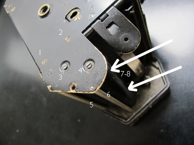 Next we will remove the left roller cover and both film guides. To do so, remove
both screws 7 and 8 inside the film compartment between both roll-film clamps. Unscrew both screws
1 and 2 on the bottom cover
plate as shown on the photo. Lift the cover just a bit to slip out the film
guides 5 and 6 out of the cover. Remove the roller cover. Now you got a nice view on
both rollers. Check if the straps are wound properly on the upper and lower side
of the inner roller (next to the mirror box). Check the outer curtain. Move both
rollers with your thumb and see if they come back on their own. That proves if
the springs are okay. Use a torch and check rollers ends for dirt.
Next we will remove the left roller cover and both film guides. To do so, remove
both screws 7 and 8 inside the film compartment between both roll-film clamps. Unscrew both screws
1 and 2 on the bottom cover
plate as shown on the photo. Lift the cover just a bit to slip out the film
guides 5 and 6 out of the cover. Remove the roller cover. Now you got a nice view on
both rollers. Check if the straps are wound properly on the upper and lower side
of the inner roller (next to the mirror box). Check the outer curtain. Move both
rollers with your thumb and see if they come back on their own. That proves if
the springs are okay. Use a torch and check rollers ends for dirt.
 Why is that so important? As we already know, both blinds when released are
starting at the same time but from different location due to the chosen (number)
gap between them. To prevent that the outer curtain will catch up or even overtake
the inner curtain and thus alter or close the gap before the inner curtain
arrives at the end of the film frame, the tension of the outer curtain should be
less than the tension of the inner curtain. Otherwise it would expose unequally
because the width of the slit would not be the same from the begin to the
end during its travel along the film surface. With as a result, there would be
an unwished gradient from light to dark on your photo.
Why is that so important? As we already know, both blinds when released are
starting at the same time but from different location due to the chosen (number)
gap between them. To prevent that the outer curtain will catch up or even overtake
the inner curtain and thus alter or close the gap before the inner curtain
arrives at the end of the film frame, the tension of the outer curtain should be
less than the tension of the inner curtain. Otherwise it would expose unequally
because the width of the slit would not be the same from the begin to the
end during its travel along the film surface. With as a result, there would be
an unwished gradient from light to dark on your photo.