Graflex National Camera Series II
Part 2
Some useful knowledge.
Many National cameras are being
offered on eBay in nonworking condition. It is an lucky exception to find a good
working one.
If you find such a working camera you undoubtedly wanted to keep it like that.
Therefore it is very important to follow exactly the instructions of the
Graflex National manual. If the shutter got stuck, it is far from easy to reset
it. The wrong sequence of setting the mirror and winding the shutter it is mostly the
reason. This focal plane
shutter with the various setting slit is the most vulnerable part of this
camera. You can feel that something is going wrong when setting the exposure
time and winding the shutter it feels too stiff.
1) Stop winding immediately and try to find the reason. You might have forgotten to set the mirror in focusing position. Let the winding knob go and pull the mirror set lever E in position. Hopefully returns the the focal plane shutter in start position again. If not, pull the Bulb release lever. The curtain might return to its start position.
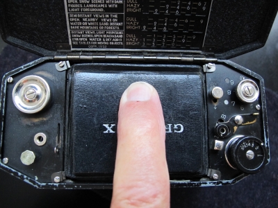
2) Check if the lens door is
open and the mirror is in focusing position you should see an image on the
ground glass.
If not, check the lens door if it is locked in open position. Press down lightly
on the lens door base.
3) The Bulb Projecting Arm setting (I) is set on B rather than on
I. Pull release arm and see what happens. By doing this you might reset
the camera is start mode.
Note: after having done this, cheque again the mirror position.
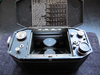
Please do spend much time in practising without film. With the
outer case removed you may observe how the shutter works.
If still possible set winding knob on "1"
Study the position of both blinds. The upper blind-the right one- should cover
the whole film frame. The left under laying blind should be partly rolled up on
the left outer roller while the begin of the blind is almost near the opposite
right blind. When winding the winding knob, both blinds should start moving
towards the right direction. Keep an ey on the Bulb Release Lever. When the clip
end of the upper blind arrives on the right film frame edge, the Bulb Release
Lever should click into the catch position, you can hear and see that happen.
Keep winding to get the left blind into the catch position. This is the end of
the shutter winding procedure. Both blinds are waiting to be released within
between them the no.1 slit representing the 1/30 second exposure.
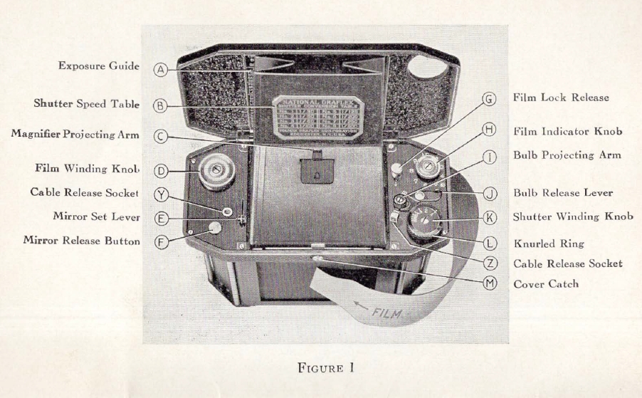
Controls explanation.
original Graflex Instruction manual.
However
If all these measurements are done without any positive result, you may consider to find the bug by
Disassembling.
But think twice before starting .
1. Remove the lens as shown in previous page 1 and open the top cover. Remove the outer case by sliding the two bottom catches in “O” position and drawing the outer case from the camera.
2. Set the mirror in viewing mode by pulling lever E and remove the view hood by removing the 4 screws and retainer clips in each corner of the view hood.
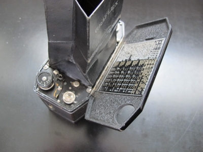
Note: The photo shows the position of the nickel plate under the winding knob
which is wrong!
This plate
should be mounted under the film winding knob on the left side and definitely
not under the winding knob!
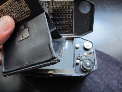
3. The ground glass is next to
be removed. It is held by two steel black pieces.
Carefully lift the glass at the rear
side of the camera. It will come off together with both black layers without any problem but better is to take a photo and draw a
mark on them to remember their position.
4. Both screws on the mirror set lever E (vintage drawing) should be unscrewed and removed.
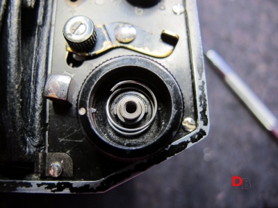
5. Unscrew and remove the mirror release lever E screw.
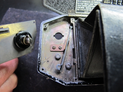
6. If not necessary do not loosen or remove the centre screw of the chrome film take up spool. The take up spool is a bit complicated. It houses 6 tiny little springs and 3 cylindrical bearings. Very difficult to replace!
7. When removed the 2 other
screws of the plate, turn the chrome take up winding key until the underlying
key matches with the hole in the camera frame and lift the plate including the
take up spool.
Beside the release arm assembly, the two lock nuts of both curtain blinds and
the mirror setting lever, the compartment is empty.
The two lock nuts together with the underlying star-washers are holding both
curtain blinds under spring tension.
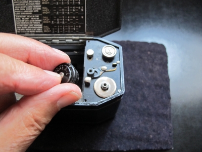
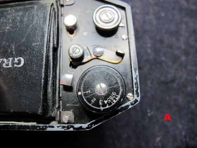
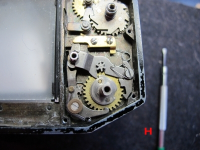
8. Now we focus our attention to the right control plate and we start with the unscrewing and removing of the frame indicator knob H.
9. Next instructions are
accompanied by the photos below.
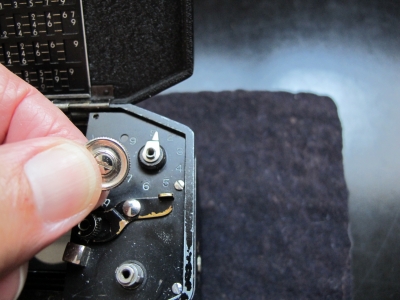
10. Set mirror lever in focus mode. Next set the Shutter Winding
Knob (K) (vintage drawing) at 1, unscrew the centre screw and remove it by lifting up.
Take photos of all positions.
Inside the cup shaped winding knob we’ll find:
a) the inner dial disk with the
numbers A
b) index plate with spacer on top
c) the index plate
d) the cup shaped outer shutter winding knob itself D.
f) upper wind tooth wheel
g) lower wind tooth wheel gear
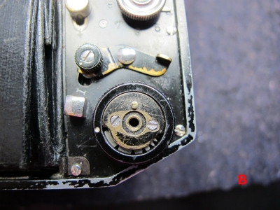
D= Remove the
gear parts out of the winding knob and at last the winding knob itself.
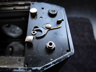
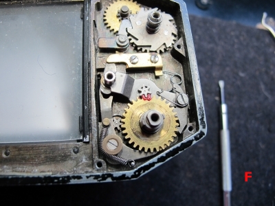
F = This is what we see after having removed the
cover plate of the right side compartment.
The top gear connected (marked with nail polish)
to the tall roller shaft of the right curtain.
H = lower tooth wheel connected to the left curtain. The winding lock out
knob in (I)-nstant mode catches into the notch of the extended plate of the lower
winding tooth wheel to stop motion of the blind.
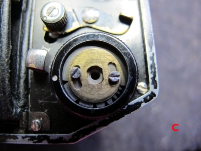
 F = Both blinds are now in "home" position, meaning that both blinds have been
pulled back by the tension of the spring loaded rollers to the left.
F = Both blinds are now in "home" position, meaning that both blinds have been
pulled back by the tension of the spring loaded rollers to the left.
The upper curtain covers the film frame completely while the underlying left
curtain disappeared in its home position
This is the best situation to start the disassembling of the mechanical
part of the focal plane shutter.
Photo F Upper tooth wheel
here marked with nail polish, matches with outer or upper curtain with long
shaft, see drawing below.
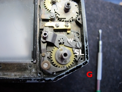
Photo G: lower tooth wheel matches with the gear of
the underlying curtain roller with low shaft.
Note the position of the Bulb/instant setting knob it lays on top of the gear to catch the projection on
the lower tooth wheel to start/ stop winding action of the lower left blind.
Both curtains are now in released (not winded) position.
W= Winding lock out knob.
SL is the set lever catch.