Unlike the earlier models of the Pacemaker Speed and Crown Graphic cameras, the Pacemaker as from 1955 is equipped with a Graphic Top Mounted Rangefinder rather than the well known side mounted Kalart Rangefinder. The top mounted Graphic rangefinder has a build in Rangelite for focusing in dimmed light. The principal feature of the new rangefinder is instantly adaptable to any of the 9 standard lenses of different focal length. This is accomplished simply by changing a small cam at the time the lens is being changed. Each interchangeable cam is matched at the factory to the lens with which it will be used and is designed to operate the rangefinder throughout the range of working distances for which the lens is intended.
Note: As there exist no 7 inch cams, the Graphic top mounted rangefinder cannot be adjusted with the 7 inch Aero lens!
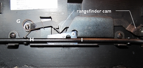
The cams are small, odd shaped metal plates that fit in a receptacle at the top of the camera. These cams serve to operate the rangefinder mirror by means of the rangefinder cam which on one end extends through the top of the camera housing. The other end "feels" the shape of the exchangeable cam and passes it through to the mirror. G keeps pressure on the rangefinder cam. The motion of the track is transmitted to the cam through a row of small steel balls encased in a tube (H) . A small plunger enters the tube at the bed end and pushes the entire row of balls through the tube. At the upper end of the tube, the last ball pushes another plunger (I) activating the cam, which in turn operates the rangefinder mirror.
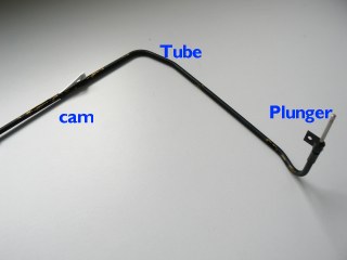
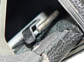
The last photo shows how the yoke bracket moves towards the plunger.
The plunger can be found on the bottom of the camera inside the housing.
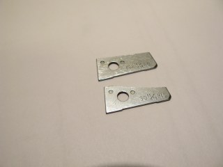
You'll need a Master Cam: 1 inch long and .032 inch thick and 0.437 inch wide, used to set infinity.
Remove the rangefinder housing by unscrewing two slotted screws on top and lift housing strait up.
Pull front standard forward and unsnap the inner cover F by lifting one and then the other of the end hooks from the slot E in the bracket tube.
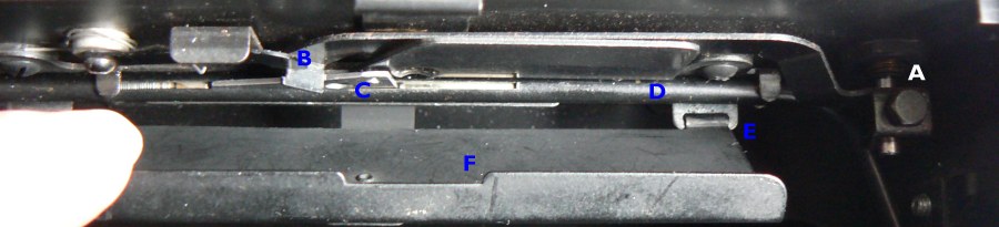
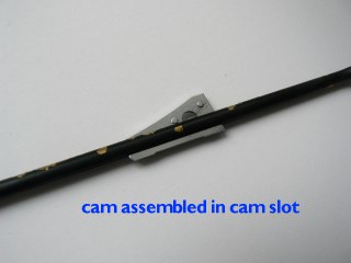
1) Assemble the master cam gage in the cam slot C. The bed yoke (track) must be back as far as possible. Assemble the yoke bracket and slide to a position that presses on the lower tube plunger to cause the master cam to line up with the edge of the rangefinder arm.
2) To set Rangefinder infinity, sight the rangefinder on a target of 500 feet or more. Move the yoke (track) forward about 1/8 inch and lock the yoke with the lever on the front right corner of the bed. Adjust the moveable mirror shaft by loosening the 3/16 inch hexagonal rangefinder arm screw A. Turn the mirror mount while observing the moveable image in the fixed mirror. When the images are aligned, tighten the hex head screw. Adjust double vision by turning the set screw on the fixed mirror mount. Observe infinity and readjust if necessary. Remove master cam.
3) Assemble the required lens cam C in the cam slot. Now focus the rangefinder at infinity and lock bed. Assemble rangefinder housing. Check the image at infinity to be sure that it has not shifted due to assembly of the housing. Unlock the bed yoke and move forward to set the scales at the nearest marked distance. Check the rangefinder image at this distance measured from the film plane to the target.
4) Focus rangefinder on infinity and lock yoke. Assemble lensboard (including the lens matching the cam) . Unlock standard lock and move front standard so that lens focuses sharp infinity target on ground glass. Use a square to check square ness of front standard on yoke. Lock standard when square and infinity is sharp. Move infinity stops against front standard and tighten flat point headless set screw on front of stop. Check ground glass, rangefinder and focusing scales at the nearest scale distance measured from the target to the film plane. Center punch yoke through the rear stop screw hole and assemble cone point headless set screw.
Same Camera: If additional lens are fitted to one camera, perform only the adjustment specified in 3 and 4
Different camera: If special lenses are to be used on a different camera, set up the infinity for the second camera as required in 1 and 2