Beseler - C6
Press Camera 4x5.
1958
Still Press Type Camera
for USA Air Force.
Originally equipped with
135-mm f/4,7 Raptar lens, Rapax synchromatic shutter and solenoid release.
Manufactured by the Charles
Beseler Company, East Orange, New Jersey.
By Jo Lommen.
Two in One
Press Camera and well
suited for Studio Work
In the
Handbook Operation and Maintenance instruction the Beseler Camera is described
as: "Still Picture, 4x5 outfit designed to
fulfil the requirements of a wide range of still, ground photography
assignments both indoors and outdoors with or without the use of synchronized
flash. In addition, the provisions for precision movements of the lens standard
make the camera well suited for studio work." Very advanced for its day
with viewfinder/rangefinder adaptable to three lenses 90 mm, 135 mm, and 250 mm.
The camera is a "press" type, which uses 4x5 inch negatives mounted in a Film
Holder or Grafmatic quick changing magazine. The camera is equipped with a self
capping focal-plane shutter and a front in-between-the-lens shutter, a coupled
rangefinder designed to operate with lenses from 90 mm to 250 mm in focal length
without changing cams, a focuspot, a sportsfinder, and an optical viewfinder
with automatic parallax correction. The back is equipped with lock bars to
secure the Grafmatic or special attachments. Spring loaded mounting arms on the
back hold the ground glass and focusing hood assemblies in place.
The Beseler Camera Housing assembly consist
of the box, the top cover assembly, the focal plane shutter, the focal
plane shutter cover, the range finder, the range finder selector, the
focuspot, the bellows and the back assembly. The principal parts of the housing
are made of aluminium die castings, painted black and partly covered with
leather. A leather carrying handle is attached to the left side of the body by
retaining clips, from which it can be quickly removed. Above the handle is the
focuspot lever which contains terminals for connection of the focuspot cable.
Immediately in front of the handle there is a finger grip which gives the
photographer a firm and comfortable hold on the camera when focusing or
shooting.
The top cover which encloses the top of the box assembly, mounts the
sportsfinder peep sight. The top cover can be removed by unscrewing the
thumbscrews to obtain easy access to the focuspot lamp. On the front of the top
cover are three windows, two for the range finder and one for the viewfinder.
Beneath these windows Is the range finder selector actuator, which permits easy
adjustment of the range finder for lenses of any focal length between 90 mm and
250 mm.
The selector indexing strip indicates the proper setting of the range finder for
the lens furnished with the camera. The indexing strip can be marked for other
lenses, as required.
The bottom forward edge of the box assembly is cast in the form of a half hinge.
This half hinge mates with another half hinge, which is cast as an integral part
of the drop bed. The drop bed, which mounts the extension assembly, is held in
the correct open position by bed struts. The drop bed is raised and snapped in
closed position when the camera is not in use. In the open position, the drop
bed serves as a support and carriage for the lens standard frame.
It is a beautiful
designed 4x5 inch camera, all black
die-cast aluminium body with all features of a technical camera such as tilt,
shift, swing, drop bed, rising front and ground glass focusing. For press work
there is a focal plane shutter available with 1/1000- 1/500 and 1/250 M or X
synchronized exposure times while T-B 1/30-1/60 and 1/100 are unsynchronised.
Fast lens exchange by a lens board latch. Further more: Build in release knob.
International back for use with double sheet film holder or quick change
magazine for 6 exposures. Retractable sports-finder. Optical view finder,
mechanical optical indicator for focusing the camera lens accurately at any
distance from 5 feet to infinity. There are flash brackets on both sides of the
camera.
The camera uses 4 by 5
negatives mounted in a film holder, film pack adapter (no longer available),
or quick-change magazine (Grafmatic
works fine!). Originally the camera is equiped with a self capping focal
plane shutter and a front (between-the-lens) shutter. Unlike the Graflex press
type cameras, the coupled rangefinder
is designed to operate with lenses from 90 mm to 250 mm in focal length without
changing cams. Furthermore a focus spot, a sports-finder and an optical
viewfinder with automatic parallax correction. The back is equiped with lock
bars to secure quick change magazine or special attachments. Spring loaded
mounting arms on the back hold the ground glass and focusing hood assemblies in
place.
Beseler History
The name Charles Beseler Company comes from Charles Beseler, a businessman in
Germany in the 19th century who sold magic lanterns and stereopticons.
Beseler died in 1909, but his company remained and then moved to New Jersey in
1919. The company manufactured photographic enlargers and other photographic
equipment throughout the 20th century. It also imported the Topcon line of
cameras into the US during the time that the company made cameras. The Charles
Beseler Company was originally founded in 1869 as a manufacturer of Inhalers,
Laryngoscopes, Magic Lanterns with Oil Lamps, High School Stereopticons, and
Museum Stereopticons.
In 1943, the company's expertise had evolved to the point where the firm became
an innovative audio-visual company primarily serving the military and education
markets with the first opaque and then overhead projection equipment. By 1953,
Beseler entered the amateur and professional photography fields. It was during
this time that the 45 Series Enlarger was born and other darkroom products were
soon developed.
Today, the Charles Beseler Company continues to be the leading supplier of
photographic darkroom equipment to the educational market. Proudly made in the
USA - at a modern manufacturing facility in Stroudsburg, Pennsylvania. Beselers' line of high-quality photographic equipment continues to withstand the
test of time and remains the industry standard for professionals and amateurs
alike.
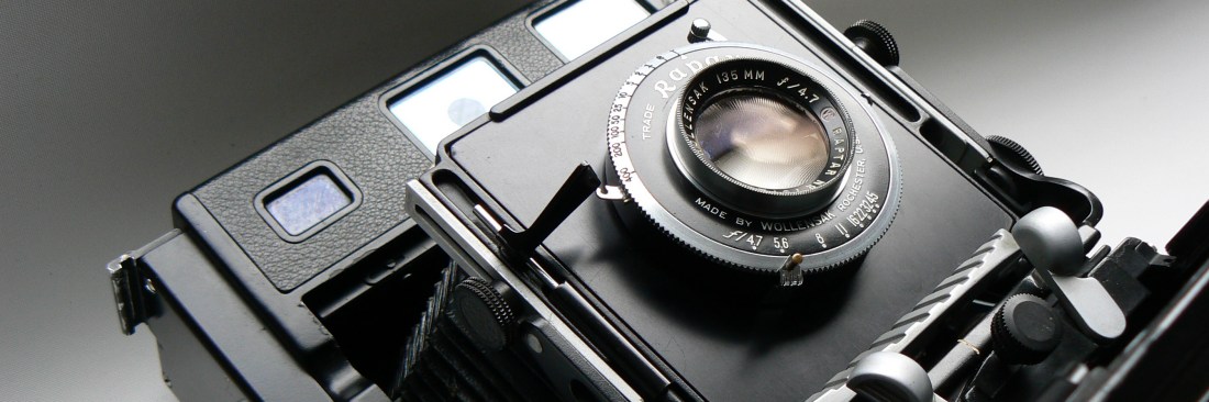
My
Beseler C 6 camera came with a
Wollensak 135 mm lens in a Rapax shutter and unfortunately missed the desirable
focal plane shutter blinds and thus the high speed press photographing feature. Also
the use of barrel lenses (lenses missing a build in leaf shutter) would
not be possible due to the lack of the above mentioned focal plane shutter. Although
the complete focal plane shutter mechanism was still present in the camera, the
blackout fabric shutter blinds were missing. These cameras were made for the US
Air Force and I can imagine why the curtains in my camera were missing. Very often these
cameras were also used for special official occasions like jubilees, award
decorations etc. These circumstances did not require fast exposures. To prevent
blank negatives as a result of a closed focal plane shutter, very often the rubberised
shutter fabric was removed to bring this risk to zero. On the other hand, the
Beseler camera front shutter could not be fired without the focal plane shutter
not being in open position. Anyway I decided to
bring the camera back in original condition by mounting new blinds into the
shutter mechanism, which was a bit more difficult than expected. Further on in
this article you can read about this successfully completed project.
Focusing
using the Range Finder
The camera is equipped with
a build in coupled mechanical rangefinder which eyepiece is situated in the
middle of the top cover. Focal range is 5 feet to infinity. It is a system of
fixed and moveable
mirrors, cams and levers, showing a double image in the
eyepiece when the object is out of focus. The correct focus is
approached when the two images are superimposed.
Beneath the windows on the front side of the
camera you'll find the range finder selector actuator (18), which permits easy
adjustment of the range finder for lenses of any focal length between 90 mm and
250 mm. The selector indexing strip (19) indicates the proper setting of the
range finder for the lens furnished with the camera. The indexing strip can be
marked for other lenses, as required.
Check if the right lens is mounted.
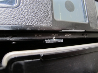
Beseler Range Finder Selector for 90, 135 and 250 mm lens.
The Focuspot is used
when illumination is not bright enough for accurate focusing by natural light. A
lamp and projection lens, working in conjunction with the rangefinder mirrors
are used to throw a a double image of the light filament on the subject when the
subject is out of focus and a single filament when the subject is in focus. The
rangefinder as well as the Focuspot works fine with the 135 mm lens mounted.
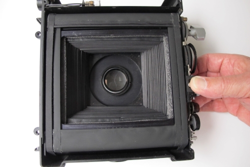
The optical viewfinder on the left side
of the top cover is marked with two frames to match with the angular field of
the lens used. The outer frame covers a 135 mm lens. The inner frame covers a
250 mm lens. You may like to check the right adjustment of the rangefinder or
just like to focus by the ground glass. This can be achieved by opening the
front lens shutter on "T".
The
shutter will stay open. The next step is to open the curtain or focal plane
shutter.
1)
Press time setting knob (3) inwards and turn
to B-T setting.
2) slide the selector
(6)button to I-B
3) turn the winding knob (1) anti clockwise until it snaps.
4) slide the - selector button (6)- downwards until it snaps.
5)The curtain runs down and stops in open position. The film frame is open
The image
will appear on the
ground glass.
Focus the subject and secure the track position by pulling the extension lock
before sliding the film holder between focusing panel and camera back.
Between-the-Lens-Shutter
Between-the-lens 5 blades
shutter. Flash connector Synchronized for M, F or X type lamps. Hand or solenoid
operated, Synchronizer equipped with "OFF" position. Cable release
socket. Shutter controls located around the shutter rim are as follows: shutter
release lever, cocking lever, press-focus lever and synchronization adjusting
lever. Speed settings Time, Bulb 1, 1/2 - 1/5 - 1/10 - 1/25 - 1/50 - 1/100 -
1/200 and 1/400 second. Flash equipment Graflite. Both sides of the camera are
equiped with a Flash Bracket. The front shutter can be released by pressing the
build in shutter release. The selector slide button 6 should be set on T which
means that the focal plane shutter stays in open position. The shutter release
knob is now coupled with the leaf shutter of the lens rather than with the focal
plane shutter. A very clever solution to prevent blind exposures.
Focal Plane Shutter.
 The focal plane shutter is
essentially two lightproof, black rubberised curtains wind on rollers. The
relative positions of the end of the curtains can be varied to provide
rectangular openings of different width for the control of shutter speed. The
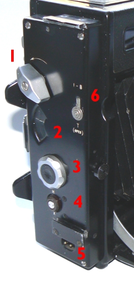
shutter controls located on the right side of the camera body consist of a
shutter winding knob (1), a time setting knob (3)
with associated shutter speed dial window (2), a selector
button (6) and a synchro knob(4).
Synchronized speeds marked on the indicator dial are: 1/1000 - 1/500 and 1/250.
The unsynchronised speeds are T (Time) - B (bulb) 1/30 - 1/50 and 1/125.
The focal plane shutter is
essentially two lightproof, black rubberised curtains wind on rollers. The
relative positions of the end of the curtains can be varied to provide
rectangular openings of different width for the control of shutter speed. The
shutter controls located on the right side of the camera body consist of a
shutter winding knob (1), a time setting knob (3)
with associated shutter speed dial window (2), a selector
button (6) and a synchro knob(4).
Synchronized speeds marked on the indicator dial are: 1/1000 - 1/500 and 1/250.
The unsynchronised speeds are T (Time) - B (bulb) 1/30 - 1/50 and 1/125.
The
selector button marked " I-B " above and " T " (open) below
is set at " I-B " for instantaneous or bulb exposures. When the focal
plane shutter is to be used for focusing on the ground glass, set dial on "B-T"
wind the shutter and then slide the selector button down to
"T" (OPEN). The shutter now runs to the open frame situation which
enables focusing on the ground glass. To close the shutter, slide the selector
back in the I-B setting.
The
synchro terminals (5) for the focal plane shutter
flash cable are located at the bottom of the control panel. A synchro knob above
and to the left of the connector is turned to the " M " index marking
when flash bulbs are to be used and to the " X " marking when
electronic flash is to be used. The shutter is self capping that means that the
shutter can be
wound without fogging the film when the dark slide of the film holder has been removed.
In other words, both blinds or curtains travel as one unit together along the
film surface not allowing light to reach the film surface.
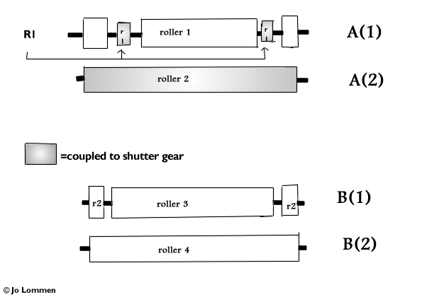
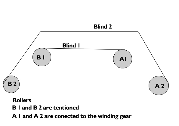
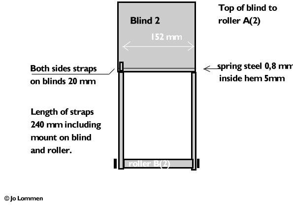
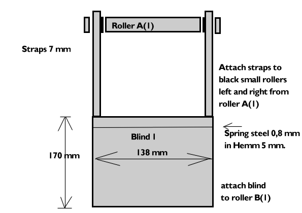
For those who are
interested to know how the curtains are positioned on the rollers, herewith some
drawings to illustrate the complicated working of the focal plane shutter. The
drawing will help you to manufacture new curtains when your camera needs new
ones. If you are in need of the blackout fabric, pleasecontact me
let me know and I'll see what I can do. Anyway make notes and take photos of
the positions of the gear before taking off the winding key. Mark their position
with nail-polish. If the old curtain is still present, take photos of the old
curtains' position on the rollers to help you when replacing the new curtains.
The
Beseler Focal Plane Shutter
Restoring Project.
The scarce information which could be found on
the internet about the Beseler camera and more specific of the focal plane
shutter forced me to find it out by myself. It was clear that the focal plane
shutter should exist out of two blinds with each two straps. First of all one
has to find out the length of each blind and its straps. Next problem was where
exactly the straps and where the blinds should be mounted to.
The most complicated part is to find out how the mechanics, winding key gears,
sprockets and speed dial should be positioned. The top rollers are connected to
the winding key gear and it is obvious that the whole exercise starts here. Both
lower rollers on the underside of the shutter are equiped with tensioned
springs. I'll spare you a long detailed and complicated explanation how this
works and confine myself to a few essential parts showed here below in four
drawings of the focal plane shutter blinds as well as two photographs of the
shutter assembly. I'm far from a professional technical designer but I tried to
make it clear how the mechanics work and how the blinds should be placed. So
please contact
me for more specific details.
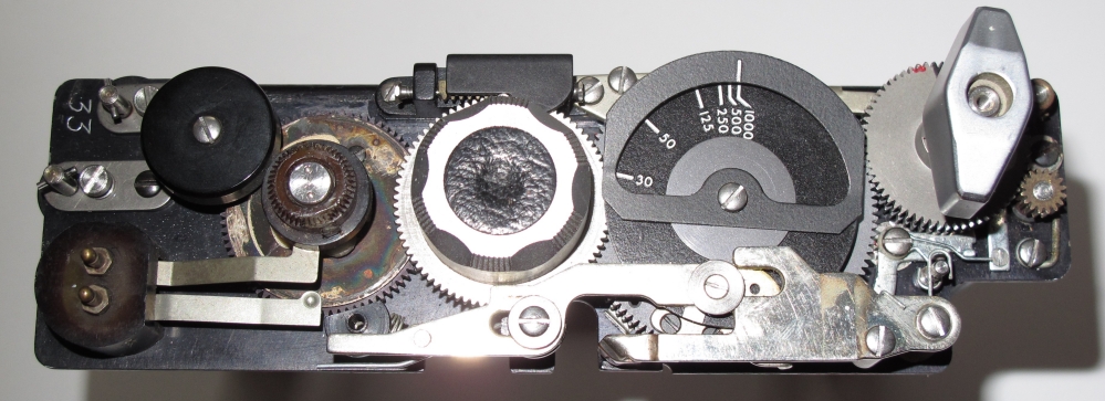
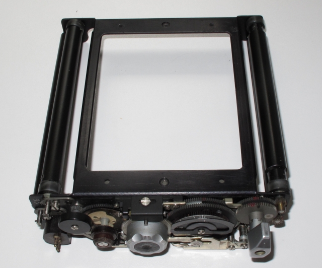
The control panel showing shutter winding key
and coupled gear, speed dial, time setting knob and synchro knob with flash
terminals.
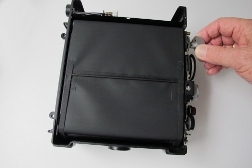
On the left the control panel cover and on the
right the stripped focal plane shutter.
These two rollers on the right are the upper
rollers and coupled to the winding key. The rollers on the left are the
lower and spring tensioned rollers.
The last two photos show the "T" exposure
procedure.
Blind 1 is partly covered by blind 2 when
winding. The self capping shutter can be wound without fogging the film even
when the dark slide has been removed. Blind 2 stays in
start position while blind 1 is drawn down when selector button is on
"T" mode and the release knob has been tripped once. When tripped the
second time, the upper blind will be released and pulled down by the lower
spring roller which closes the film
frame and thus finishes the exposure. The "I-B" mode is in fact the
same procedure but the exposure runs by pressing the release button only one
time. The width of the slit provides the exposure time. Note: the spring tension
always stays equal regardless the width of the slit.
Loading Camera
Prepare camera back. Slide both slide locks to
the right. Slide the ground glass assembly into the lock bars. Insert the loaded
film holder between the back of the camera house and the ground glass assembly.
A slight backward pressure on the "ears" of the ground glass assembly
will move the frame back and facilitate insertion of the film holder. The holder
slides easily into its position. The tension of the ground glass assembly holds
the film holder tight against the camera housing thus preventing light coming
in. Draw dark slide and expose. After exposure don't forget to push back the
dark slide. You may insert the Grafmatic
holder the same way as the double film holder.
Exposure using the Focal Plane Shutter.
Set the front shutter in "T"
position. Cock the shutter and trip the release lever. The shutter opens and
stays "OPEN" allowing the use of the Focal plane shutter. Set the
focal plane shutter selector button (6) on
"I-B" position. As we already opened the front shutter, you may now
choose the exposure speed of the focal plane shutter by using the time setting
knob (3) on the side control
cover. Depress the time setting knob and turn it into the desired position
opposite the index mark on the speed indicator (2)
dial. Release the knob and let it snap into the nearest detent. Now wind the
winding knob anti-clockwise until it reaches a full stop. The shutter is now
cocked and ready for tripping.
Exposure using the Between-the-Lens Shutter.
It is the other way around. Make sure that the Focal
Plane shutter is in "Open" position. To do this, set the time
setting knob on B-T and wind the shutter anti clockwise following the arrow. Now
slide the "I-B " selector button down in "T" position.
The lower blind will be drawn down while the upper blind stays in the upper
position. The Focal Plane shutter is in "OPEN" position and thus
allowing the use of the front shutter.
More Lens Movements.
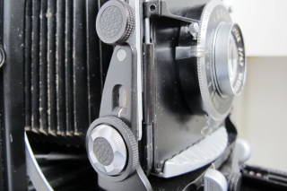
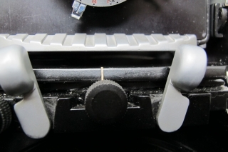
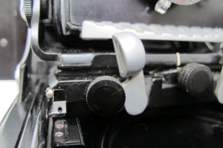
Left: Rising Front Knob - Middle: Lateral Shift
Knob and standard lock levers - Right: Lateral Swing Knob.
As mentioned before the Beseler camera is well
suited for studio work. The lens standard assembly consist of the lens board
with shutter/lens assembly, a lens standard frame assembly and support and the
sports finder assembly. On the sides of the lensboard frame assembly you'll find
the rising front lock knobs, the lens tilt and lens tilt lock
knobs used to swing the front about a horizontal axis. Furthermore
the body cable release tripper that operates the front shutter release lever.
The sportsfinder assembly slides down into grooves in the sides of the lens
board frame assembly. When the sportsfinder is pulled up into operating
position, it is used in conjunction with the peep sight on the top cover. The
lens standard support includes lens standard lock levers to hold the support in
place within the camera box or on the drop bed and extension assembly.
Furthermore a lateral swing knob used to swing the front standard about a
vertical axis and a lateral shift knob that is pulled out and rotated to
move the lens standard laterally. The lensboard frame assembly is connected to
the inside of the camera box by a light tight bellows. Note: The lens standard
assembly cannot be pushed back into the body of the camera until the extension
assembly has completely retracted (by turning the focusing knobs), in which
position the pins are depressed by the entry of two flat springs at the rear of
the rails into the rear of the bed. Thus the lens standard cannot accidentally
be pushed back off the extension track. All these features together with a nice
and ergonomic design, makes the Beseler an attractive Press Camera, for the
collector as well as for the practising amateur or professional photographer.
Beseler
Rangefinder chain repair
Jo Lommen Classic
Cameras